123
Scheduled Maintenance
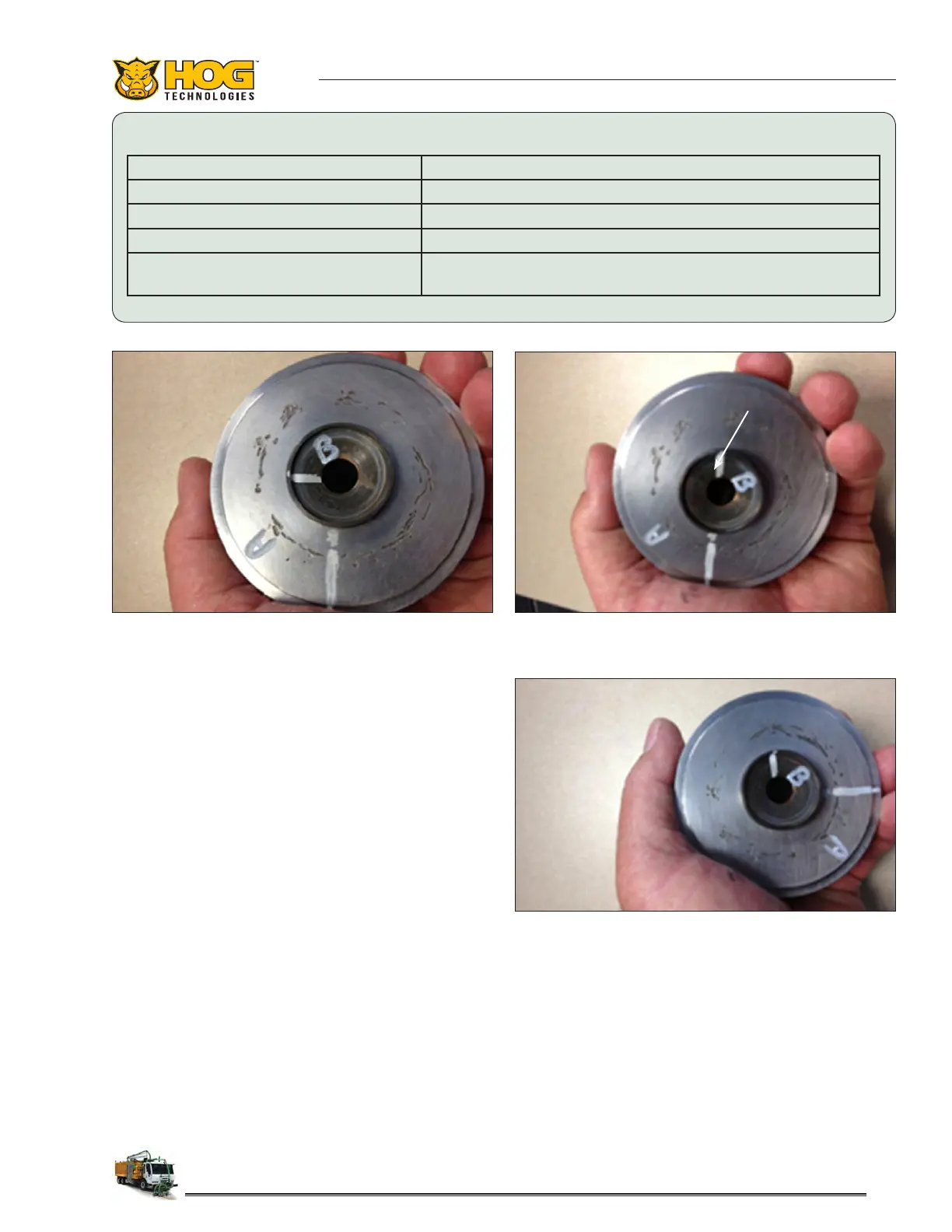
Figure 2: A. Univalve Body - B. Suction Valve
Valve Cartridge Rotated 90
0
Counterclockwise
Figure 4: A. Univalve Body - B. Suction Valve
Valve Cartridge Rotated 90
0
Clockwise
Figure 3: A. Univalve Body - B. Suction Valve
Suction Valve Rotated 90
0
Clockwise
Shiny Line Indicates a cut or a crack
Cuts caused by a leak Can be lapped if not too deep
Cracks in the univalve Cannot be repaired, replace the univalve
Shiny dot is a pit caused by calcium Can be lapped out
“V” shape on top of a hole Can be lapped out, check the inner wall of the univalve
for damage
LEGEND
6. Use approximately 5 lbs of pressure on the
suction valve (B), and rotate it 180 degrees
clockwise, then 180 degrees counterclockwise
on the valve cartridge seat (A).
7. Each 180 degree clockwise/180 degree coun-
terclockwise movement is considered one
rotation. Complete 5 rotations.
8. Rotate valve cartridge (A) 90 degrees coun-
terclockwise while maintaining the position
of suction valve (B). Repeat steps 6 and 7.
Figure 2.
9. Rotate suction valve (B) 90 degrees clockwise
while maintaining the position of valve car-
tridge (A). Repeat 6 and 7. Figure 3.
10. Rotate valve cartridge (A) 90 degrees coun-
terclockwise while maintaining the position
of suction valve (B). Repeat steps 6 and 7.
Figure 4.
11. Continue steps 6-9 for 2 minutes at about 120
rotations per minute.
12. Remove the suction valve and clean both
pieces thoroughly with brake cleaner. Be sure
to thoroughly clean the holes in the UNI-VALVE
to ensure no debris can get in the new grit.
Blow o the components with compressed air
after cleaning them with brake cleaner.
Steps 3-11 = One Cycle
 Loading...