3232
Stripe Hog Systems
Refer to the Wear Brush in this section and the
Maintenance section of this manual for additional
information on adjusting and replacing the wear
brush.
NOTICE:
ALWAYS MAKE SURE TO CHECK THE HOG HEAD FOR
SMOOTH AND PROPER OPERATION BEFORE EACH SHIFT.
DO NOT USE EQUIPMENT THAT HAS NOT BEEN CHECKED
THOROUGHLY.
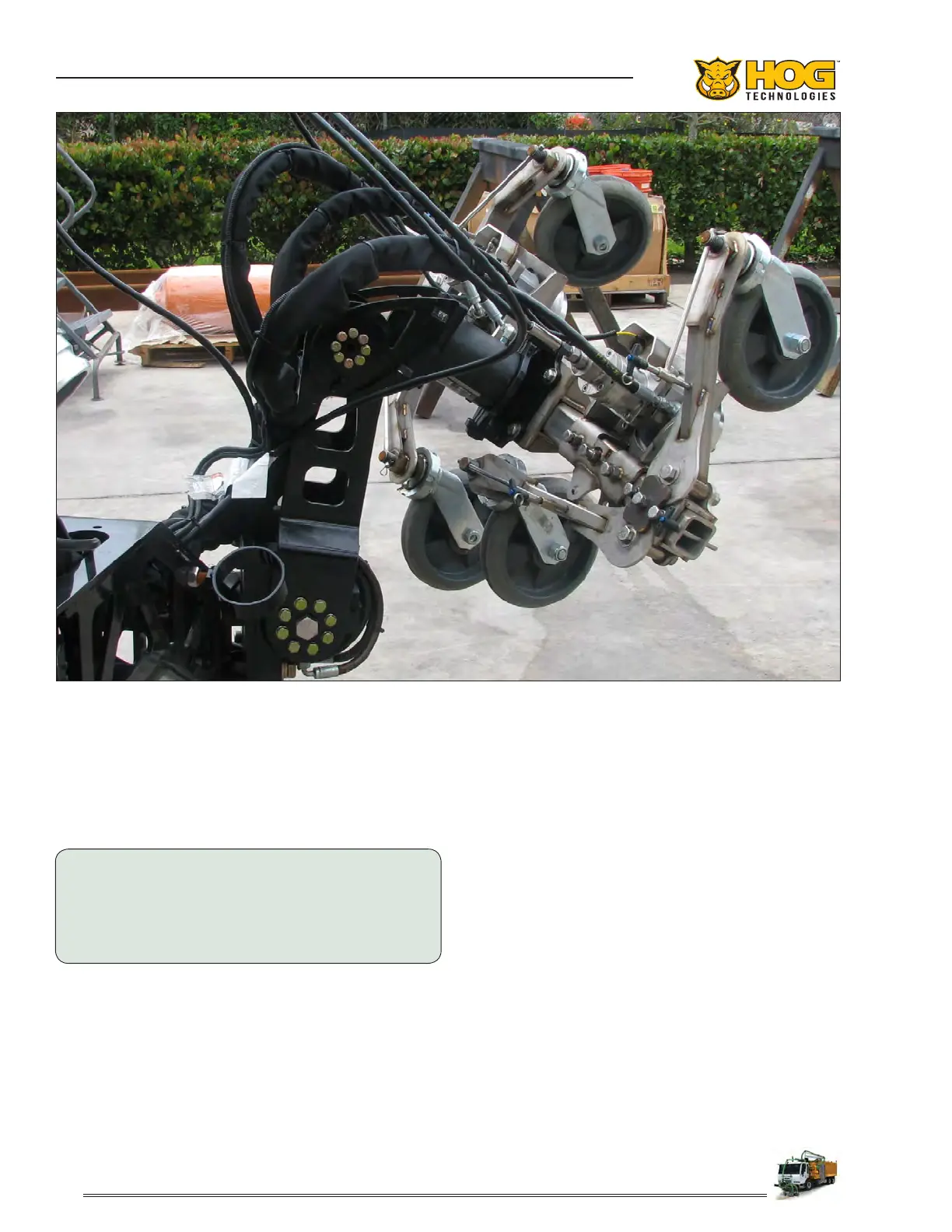
The exible design of the tubular head plate al-
lows the operator to congure the blasting heads
in a variety of congurations to accommodate
dierent waterblasting operations. The heads can
mounted together on either side of the arm or
one blasting head on each side of the arm. The
distance between the blasting heads or from the
helac cylinder to the blasting head is also adjust-
able. Special brackets with jam bolts and nuts
secure the spray heads and other tubular head
plate components in the desired position.
The blasting heads operate simultaneously when
activated by the UHP system and the start button
in joystick console. The spray bars are rotated by
special hydraulic powered motors called thru-shaft
motors. The center of the rotating shaft is drilled
to allow high pressure water to pass through the
shaft to the spray bar. Spray bar rotation is con-
trolled by the PLC (Programmable Logic Controller)
and the Head Rotation speed dial on the joystick
console.
Spray bar rotation in each blasting head can be
independently controlled by the PLC, which allows
the operator to choose various speeds between
700 and 3000 RPM or simultaneously controlled
using the Head Rotation speed dial. Two operating
Tubular Head Plate, Castor Wheels & Arms
 Loading...