3333
Stripe Hog Systems
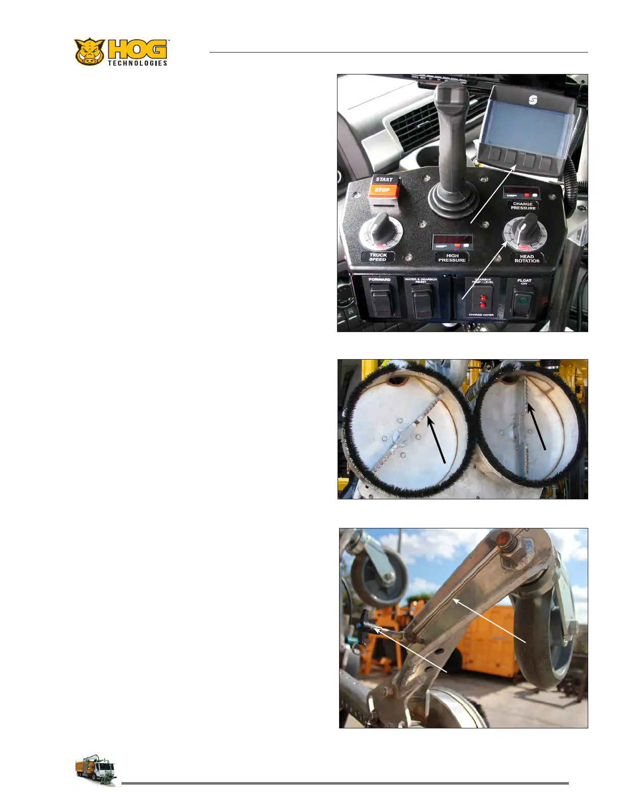
modes are available, manual and automatic. In
manual mode, the rotation speed of each spray
bar is controlled simultaneously by the Head Rota-
tion speed dial on the Joystick console. In auto-
matic mode, the operator uses the PLC to set the
maximum RPM for each spray bar, then uses the
Head Rotation dial to adjust rotation speed from
0 to the preset maximum. The PLC also enables
operators to program and store preset speeds for
each spray bar in the memory.
The double blasting head design allows the blast-
ing heads to swivel which enables the operator
to control the width of the blast area or set the
blasting heads to remove two separate lines at the
same time. Additionally, the operator can choose
to use dierent length spray bars on each blasting
head to remove two lines of dierent widths simul-
taneously or when removing one line with heavy
paint buildup and another line with thinner paint.
The operator can swivel the heads to any orien-
tation from inside the cab using controls in the
joystick console. A helac cylinder at the end of
the arm rotates the tubular head plate to set the
blasting heads to the desired orientation. Addi-
tional adjustments can be made during operation
by swiveling the blasting head chassis with the
helac cylinder or by moving the arm left or right.
The tubular head plate is equipped with three
or four adjustable heavy duty castors wheels
that support the blasting heads and prevent the
spray bars and shrouds from touching the road
surface. The castor wheels are attached to heavy
duty arms mounted to the tubular head plate.
The arms swivel to allow the wheel location to be
adjusted to avoid hazards such as rumble strips
and road reectors or to accommodate other op-
erating situations. The arms are secured in posi-
tion by adjustable friction plates with a bolt and
jam nut locking system. The arms are adjusted
by loosening the jam nut and moving the arm to
the desired position. Then tighten the jam nut to
secure the arm.
The castor wheel mount assemblies are threaded
to provide spray bar/blasting head height adjust-
ment. Adjustment rods attached to each castor
wheel assembly are used to rotate the threaded
shaft to move the wheels up or down. The rods are
secured to the arms with T-handle pins to lock the
castor wheel assemblies and blasting heads at the
desired height. Blasting head height adjustment
Typical Blasting heads Showing Spray Bars
Caster Wheel Adjustment Rod & T-Handle Pin
Joystick Console, Head Rotation Speed Dial & PLC
 Loading...