Rev. 1.50 48 August 28, 2017 Rev. 1.50 49 August 28, 2017
HT66F0175/HT66F0185
A/D Flash MCU with EEPROM
HT66F0175/HT66F0185
A/D Flash MCU with EEPROM
Bit2 HTO:Highspeedsystemoscillatorreadyag
0:Notready
1:Ready
Thisisthehighspeedsystemoscillatorreadyflagwhichindicateswhenthehigh
speedsystemoscillatorisstable.Thisflagisclearedto“0”byhardwarewhenthe
devicesarepoweredonandthenchangestoahighlevelafterthehighspeedsystem
oscillatorisstable.
Thereforethisagwillalwaysbereadas“1”bytheapplicationprogramafterdevice
power-on.TheagwillbelowwhenintheSLEEPorIDLE0Modebutafterawake-
uphasoccurred,theagwillchangetoahighlevelafter512clockcyclesiftheHXT
oscillatorisusedandafter15~16clockcyclesiftheHIRCoscillatorisused.
Bit1 IDLEN:IDLEmodecontrol
0:Disable
1:Enable
ThisistheIDLEmodecontrolbitanddetermineswhathappenswhentheHALT
instructionisexecuted.Ifthisbitishigh,whenaHALTinstructionisexecured,the
devicewillentertheIDLEmode.IntheIDLEmodetheCPUwillstoprunningbut
thesystemclockwillcontinyetokeeptheperipheralfunctionsoperational,ifthe
FSYSONbitishigh.IftheFSYSONbitislow,theCPUandthesystemclockwillall
stopinIDLE0mode.Ifthebitislow,thedeviceswillentertheSLEEPmodewhena
HALTinstructionisexecuted.
Bit0 HLCLK:Systemclockselection
0:f
H
/2~f
H
/64orf
SUB
1:f
H
Thisbitisusedtoselectifthef
H
clockorthef
H
/2~f
H
/64orf
SUB
clockisusedas
thesystemclock.Whenthebitishighthef
H
clockwillbeselectedandiflowthe
f
H
/2~f
H
/64orf
SUB
clockwillbeselected.Whensystemclockswitchesfromthef
H
clocktothef
SUB
clockandthef
H
clockwillbeautomaticallyswitchedofftoconserve
power.
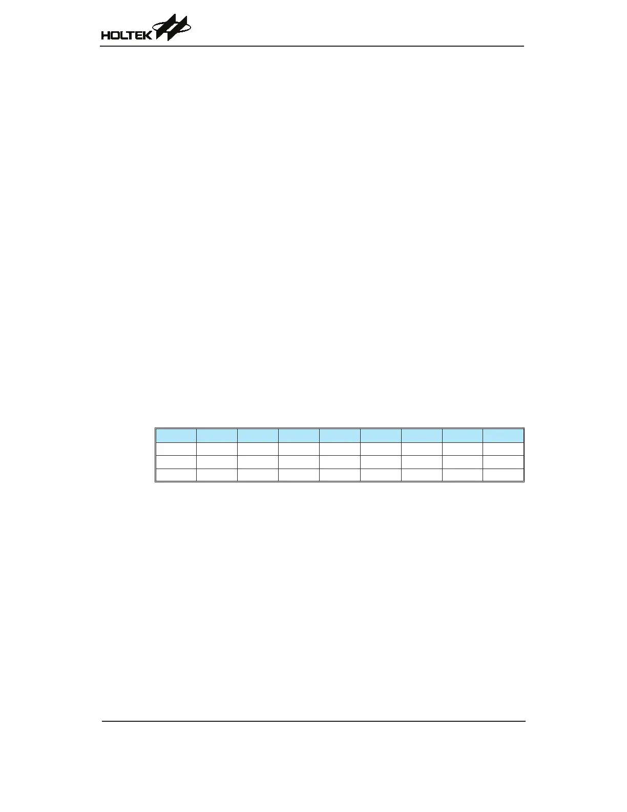
CTRL Register
Bit 7 6 5 4 3 2 1 0
Name FSYSON — — — — LVRF LRF WRF
R/W R/W — — — — R/W R/W R/W
POR 0 — — — — x 0 0
“x”: unknown
Bit7 FSYSON:f
SYS
ControlinIDLEMode
0:Disable
1:Enable
ThisbitisusedtocontrolwhetherthesystemclockisswitchedonornotintheIDLE
Mode.Ifthisbitissetto“0”,thesystemclockwillbeswitchedoffintheIDLEMode.
However,thesystemclockwillbeswitchedonintheIDLEModewhentheFSYSON
bitissetto“1”.
Bit6~3 Unimplemented,readas“0”
Bit2 LVRF:LVRfunctionresetag
Describedelsewhere.
Bit1 LRF:LVRcontrolregistersoftwareresetag
Describedelsewhere.
Bit0 WRF:WDTcontrolregistersoftwareresetag
Describedelsewhere.