LOWER CHAMBER
SIDE
BLOW PRESSURE
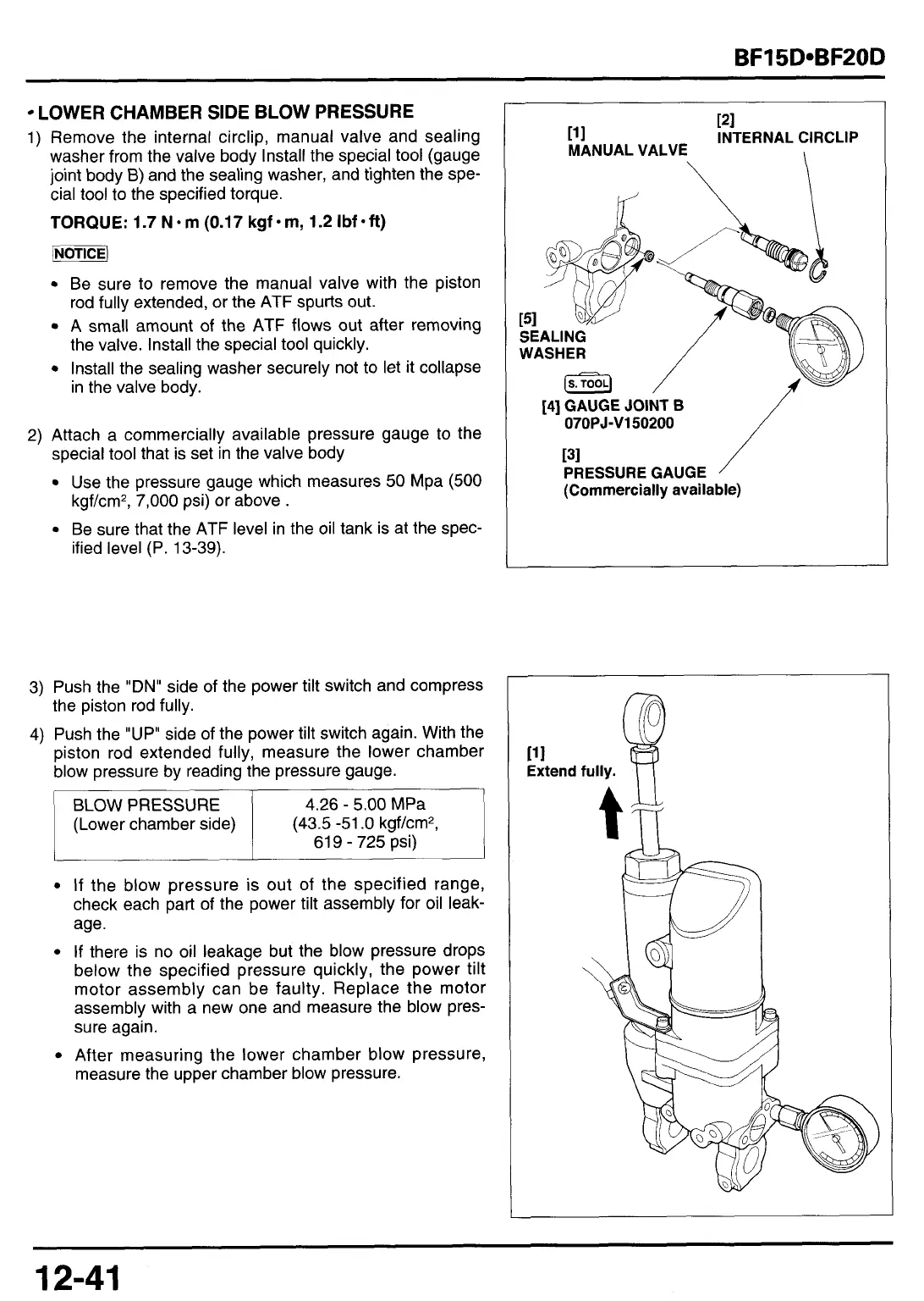
1) Remove the internal circlip, manual valve and sealing
washer from the valve body Install the special tool (gauge
joint body
B)
and the sealing washer, and tighten the spe-
cial tool to the specified torque.
TORQUE:
1.7 N-m (0.17 kgf-m, 1.2 Ibf-ft)
pi\
Be sure
to
remove the manual valve with the piston
rod fully extended, or the ATF spurts out.
A
small amount
of
the
ATF
flows out after removing
the valve. Install the special
tool
quickly.
Install the sealing washer securely not
to
let
it
collapse
in the valve body.
BLOW
PRESSURE
(Lower chamber side)
2)
Attach a commercially available pressure gauge
to
the
special
tool
that is set in the valve body
Use the pressure gauge which measures
50
Mpa
(500
kgf/cm*,
7,000
psi) or above
.
Be sure that the ATF level in the oil tank is at the spec-
ified level (P. 13-39).
4.26
-
5.00
MPa
(43.5
-51
.O
kgf/cm2,
61
9
-
725
psi)
If
the blow pressure is out of the specified range,
check each part of the power tilt assembly for oil leak-
age.
If
there is no oil leakage but the blow pressure drops
below the specified pressure quickly, the power tilt
motor assembly can be faulty. Replace the motor
assembly with a new one and measure the blow pres-
sure again.
After measuring the lower chamber blow pressure,
measure the upper chamber blow pressure.
121
111 INTERNAL ClRCLlP
MANUAL VALVE
\
\
121
111 INTERNAL ClRCLlP
MANUAL VALVE
\
\
141
GAUGE
JOINT
B
07OPJ-V150200
131
PRESSURE GAUGE
(Commercially available)
12-41



 To Next Page