Mounting and Wiring the Control
2-9
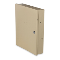
4219/4229 Expansion Zones
1. Connect each module to the control’s keypad
terminals.
2. Assign the module a device address of 08
using its DIP switches. The device address
determines the zone numbers being used, as
shown below.
Expander Module Addresses
Zones… Device Address…
17-24 08
3. Connect sensors to the module’s loops.
4. If using relays with the 4229, connect the
desired field wiring to the unit's relay
contact terminals.
Notes
• Supports up to 8 expansion zones (NO or NC)
using 4219/4229 Zone Expander Modules as
follows:
• Use 1000 ohm end-of-line resistors at the end
of loops connected to the 4219/4229 modules.
(End-of line resistors used on the control
terminals are 2000 ohms.)
• Expansion zones have normal response time
(400–500 msec), except zone connected to each
module’s loop “A,” which can be set for fast
response† (10–15 msec).
† Do not use fast response in Western Europe;
fast response is not permitted by
EN50131-1/prEN50131-3.
BRN
GRN
BLK
(–) GROUND
RED
(+) 12VDC
YEL
4
3
2
1
ZONES
A
B
C
D
F
GH
DIP SWITCH
FOR SETTING ADDRESS
AND ZONE "A" RESPONSE
TAMPER JUMPER POSITION
4229 IN CABINET
(NOT TAMPER)
4229 REMOTE
(TAMPER PROTECTED)
TB1
4229
TB2
WHT
GRY
VIO
BLK
YEL
ORG
NO
NC
C
GND
NO
NC
C
RLY
1
RLY
2
RELAYS OFF
RELAY
CONNECTOR
RELAY
2
RELAY
1
(TERM 6)
(TERM 4)
(TERM 5)
(TERM 7)
NO C NC
TERMINALS ON
CONTROL PANEL
1
2
3
4
DATA OUT (>)
TO CONTROL
DATA IN (<)
FROM
CONTROL
5
8
11
REED
(TAMPER)
SWITCH
2
E
1
3
4 6
7
9
10
12
TERMINATE EACH
PROGRAMMED ZONE
WITH 1000 OHM (1K)
END-OF-LINE RESISTOR
(EACH ZONE'S MAX.
LOOP RESISTANCE
300 OHMS + EOL)
4-PIN CONSOLE PLUG
EITHER OR BOTH CAN BE USED
4229-002-V0
Figure 7. Wiring Connections, 4219 & 4229 (4229 shown)

 Loading...