CGW-MB Installation and Users’ Manual | P/N:LS10248-000HW-E | REV.G | JUL/31/2022 181
Triga Panels Connecting to the Panels
C.13 Triga Panels
C.13.1 Connection Options
The CLSS Gateway mainboard operates only with the Triga fire alarm control panels as
listed in the table below:
Table C.11: Triga Panel Connection Options
Minimum Required Versions
For the Panel: 6.05.01
For the CGW-MB: 3.1.4.74
C.13.2 To Use an RS-485 Connection
Using an RS-485 cable the CGW-MB connects with the annunciator primary terminal of
the panel.
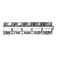
1. On the CLSS Gateway mainboard Side
At the RS-485 A port in the CLSS Gateway mainboard board:
• Connect the A connector to the IN+ pin of the RS-485 A port.
• Connect the B connector to the IN- pin of the same RS-485 A port.
The RS-485 ports in the CLSS Gateway mainboard board are labeled as 3 and 4 in the
Figure C.2.
2. On the Panel Side
At the S-BUS board in the ANN-BUS PRI terminal:
• Connect the RS-485 +ve wire to the A port.
• Connect the RS-485 -ve wire to the B port.
3. Power Connection
On the CLSS Gateway mainboard Side
In the power supply port (labeled 7 in the Figure C.2):
• Connect the Red wire to the +24V pin.
• Connect the Black wire to the Gnd pin.
On the Panel Side
In the power board of the panel:
• Connect the Red wire to the +ve pin.
• Connect the Black wire to the -ve pin.
Fire Alarm Panel Models RS-485 UART/TTL RS-232 USB
TR-75R Yes No No No
TR-75B Yes No No No
TR-2100R Yes No No No
TR-2100B Yes No No No
TR-R2100R Yes No No No
TR-R2100B Yes No No No
TR-2100ECSR Yes No No No
TR-2100ECSB Yes No No No
CAUTION: WHEN SUPPORTING THE ALARM TRANSMISSION, IT IS RECOMMENDED THAT THE TRIGA
PANEL SHOULD USE SECONDARY ANN BUS CHANNEL WITH CLASS A WIRING.
IF THE ALARM TRANSMISSION SERVICE IS NOT USED, THE PANEL CAN USE EITHER THE PRIMARY OR
THE SECONDARY ANN BUS CHANNEL FOR THE CGW-MB CONNECTION.
CAUTION: CONNECT EITHER THE CGW-MB OR THE ANN S/P G MODULE WITH THE PANEL. BOTH OF
THEM SHOULD NOT BE CONNECTED TOGETHER WITH THE PANEL.

 Loading...