CGW-MB Installation and Users’ Manual | P/N:LS10248-000HW-E | REV.G | JUL/31/2022 17
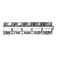
CLSS Gateway mainboard Board Layout Overview
2.3.2 LED Indicators
The LED indicators on the CLSS Gateway mainboard board use different colors to
identify the operational status of the CLSS Gateway mainboard. To know the location of
the LED indicators on the CLSS Gateway mainboard board, refer to
Figure 2.1, “Printed
Circuit Board: Layout”
.
Figure 2.2: The LED Indicators on the CLSS Gateway mainboard
Table 2.2: LED Indicators and Their Messages
SOM
Power-Indicating LED
Indicates the CLSS Gateway mainboard board’s received power status. See “Power
Indicator” in
Figure 2.1
.
ON The circuit board is receiving 24V power from its power source.
OFF The circuit board is not receiving power.
DL1
LTE Power LED
Indicates the power supply status for cellular communications
ON The LTE radio device is receiving power from the circuit board.
OFF The LTE radio device is not receiving power.
DL2
Trouble LED
Indicates the CLSS Gateway mainboard’s operational status
OFF There are no issues.
FLASHING SLOW (flashes once per 1 second) There are communication
issues with the panel or the Internet connectivity.
ON There is a critical error in the system.
To fix the issues, you can refer to the
6.2, "Troubleshooting"
section, which
discusses about some possible issues and their solutions.
DL6
Mobile Connectivity LED
Indicates the status of mobile communications between the CLSS Gateway
mainboard and the CLSS App.
FLASHING SLOW (flashes once per 1 second) The CLSS Gateway
mainboard is connected to the CLSS App.
FLASHING FAST (flashes once per 0.25 second) The CLSS Gateway
mainboard is ready for the CLSS App connection.
OFF The mobile connectivity is disabled.

 Loading...