6 Assembly Instructions
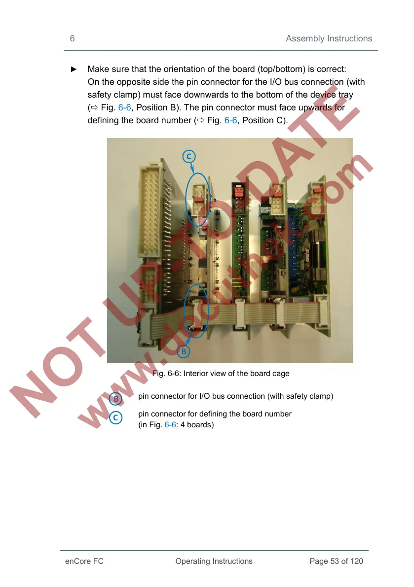
► Make sure that the orientation of the board (top/bottom) is correct:
On the opposite side the pin connector for the I/O bus connection (with
safety clamp) must face downwards to the bottom of the device tray
( Fig. 6-6, Position B). The pin connector must face upwards for
defining the board number ( Fig. 6-6, Position C).
Fig. 6-6: Interior view of the board cage
pin connector for I/O bus connection (with safety clamp)
pin connector for defining the board number
(in Fig. 6-6: 4 boards)
 Loading...


