EasyManuals Logo

Honeywell enCore FC Series User Manual

Honeywell enCore FC Series
133 pages
To Next Page IconTo Next Page
To Previous Page IconTo Previous Page
Page #52 background imageLoading...
Page #52 background image
Assembly Instructions 6
Page 52 of 120
Operating Instructions
enCore FC
Set up the board number on the board
Note that the number of the board slot as well as the board
number on the board must be set; this is essential for further
functioning of the internal I/O bus communication.
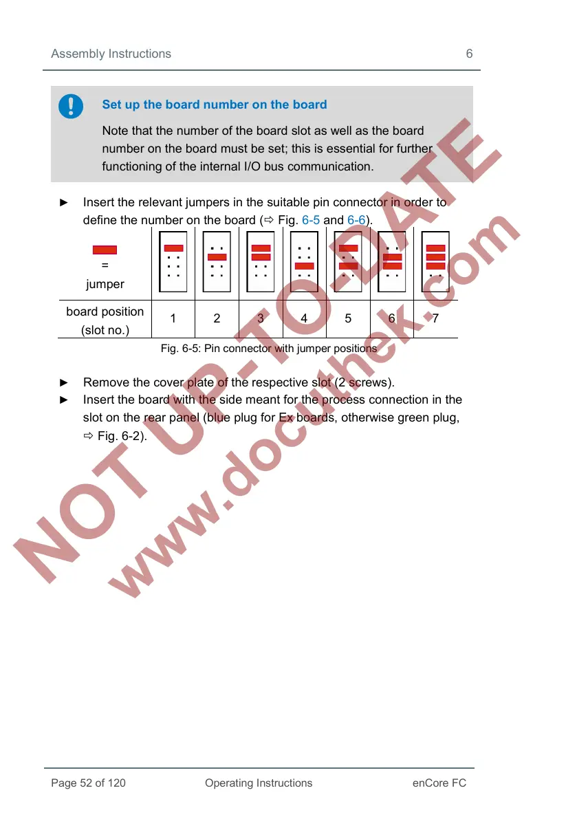
Insert the relevant jumpers in the suitable pin connector in order to
define the number on the board ( Fig. 6-5 and 6-6).
=
jumper
board position
(slot no.)
1 2 3 4 5 6 7
Fig. 6-5: Pin connector with jumper positions
Remove the cover plate of the respective slot (2 screws).
Insert the board with the side meant for the process connection in the
slot on the rear panel (blue plug for Ex boards, otherwise green plug,
Fig. 6-2).

Table of Contents

Other manuals for Honeywell enCore FC Series

Questions and Answers:

Question and Answer IconNeed help?

Do you have a question about the Honeywell enCore FC Series and is the answer not in the manual?

Honeywell enCore FC Series Specifications

General IconGeneral
BrandHoneywell
ModelenCore FC Series
CategoryDesktop
LanguageEnglish

Related product manuals