10 IFP-75 Series Manual — P/N LS10147-001SK-E:E 4/6/2022
Introduction About this Manual
1.2 About this Manual
This manual is intended to be a complete reference for all installation and operation tasks for the IFP-75.
1.2.1 Terms Used in this Manual
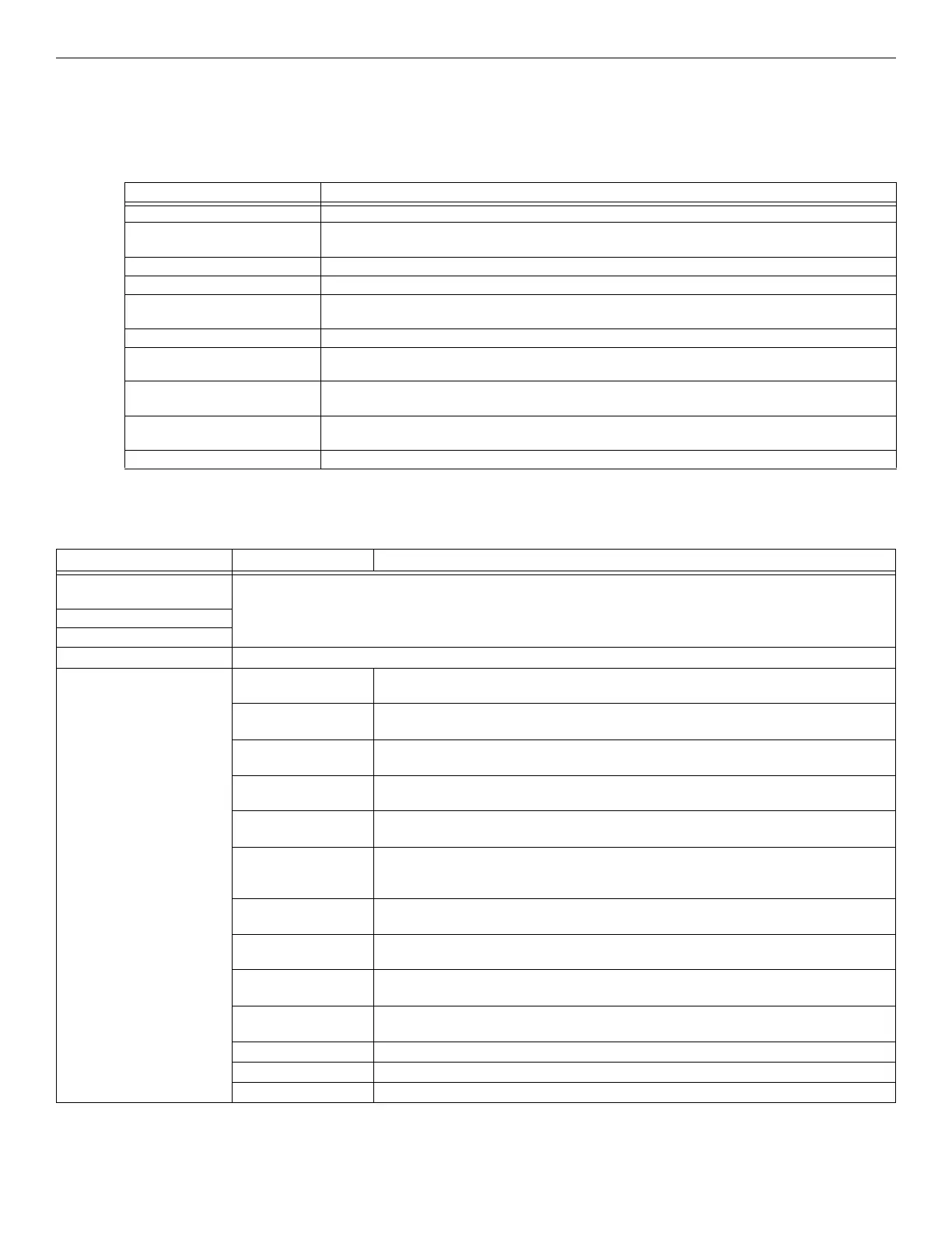
The following terminology is used with the IFP-75 system:
1.3 Compatible Products
The chart below lists the products available for use with the IFP-75.
Term Description
SLC Signaling Line Circuit
Module The term module is used for all hardware devices except for SLC addressable devices and notification
appliances. This includes the IFP-75 panel itself.
Input Point An addressable sensing device, such as a smoke or heat detector or a contact monitor device.
Input Zone A protected area made up of input points.
Output Point (or Output Circuit) A notification point or circuit for notification appliances. Relay circuits and auxiliary power circuits are also
considered output points.
Group (or “Output Group”) A group of output points. Operating characteristics are common to all output points in the group.
Output (or “Cadence”) Pattern The pattern that the output will use, for example, Constant, March Code, ANSI 3.41. Applies to zones
and special system events. See Appendix D for additional information.
Mapping Mapping is the process of specifying which outputs are activated when certain events occur in the
system. Figure 7.2 describes mapping in detail.
Network System Consists of any combination of 32 panels of these model numbers: IFP-75, IFP-300, IFP-300ECS, IFP-
2100, or IFP-2100ECS.
SWIFT Smart Wireless Integrated Fire Technology
Table 1.1 Manual Terminology
Type of Device Model Description
IDP Addressable SLC
Devices
For a list of compatible devices, refer to the SLC Wiring Manual, P/N: LS10179-000FH-E.
SK Addressable SLC Devices
SD Addressable SLC Devices
SWIFT Wireless SLC Devices For a list of compatible devices, refer to the SWIFT Manual, P/N: LS10036-000FH-E.
Other Modules 5824 Serial/Parallel
Printer Interface Module
Allows a printer to be attached for the on-site event logging. Maximum of four 5824s per
control panel.
RPS-1000 Power
Supply
Provides additional power, six Flexput circuits, and two Form C relays. Max 8 per system. See
RPS-1000 Installation Manual (PN 151153) for more information.
5496 NAC Expander Provides 4 additional Notification Appliance Circuits/Auxiliary power. (Up to 8 per IFP-75
System).
RA-100 and RA-1000R
LCD Annunciator
4 x20 Remote LCD annunciator. Can be used in any combination, up to a total of 8 devices on
one panel.
RA-2000LCD
Annunciator
4 x 40 Remote LCD annunciator can be used in any combination, up to a total of 8 devices on
one panel.
5865-3 and
5865-4 LED
Annunciator
LED annunciator can display up to 30 LEDs (15 red and 15 yellow). 5865-4 has key switches
for silence and reset, and a system trouble LED. 5865-3, 5865-4, and 5880 can be used in
any combination, up to a total of eight devices on one panel.
RA-100TG/R Trim
Rings
Trim ring kit for surface mounting the RA-2000/RA-100 annunciators.
5860TG and 5860TR
Trim Rings
Trim ring kits for surface mounting the RA-1000/R annunciator. 5860TG is gray; 5860TR is
red.
5880 LED Driver
Module
Driver for up to 40 LEDs. Interfaces with customized annunciator boards. In addition the 5880
has eight generic switch input points.
5883 General Purpose
Relay Module
Provides 10 Form C relays. Designed to be driven by the 5880. Up to four, 5883s can be used
with each 5880 module.
SK-NIC Network Interface Card
SK-FML Fiber-Optic Multi Mode
SK-FSL Fiber-Optic Single Mode
Table 1.2 IFP-75 Compatible Products
 Loading...


