26 IFP-75 Series Manual — P/N LS10147-001SK-E:E 4/6/2022
Section 4: Control Panel Installation
4.1 Mounting the Control Panel Cabinet
Read the Environmental Specifications in Section 3.2 before mounting the IFP-75 panel.
The IFP-75 cabinet base dimensions are: 12.531” W x 14.875” H.
The IFP-75 panel should be located within a secured area, where it is accessible to the main drop wiring runs and where it can be easily
tested and serviced. End-users responsible for maintaining the panel should be able to hear alarms and troubles. When you select a location,
keep in mind that the panel itself is the main source of alarm and trouble annunciation.
When mounting on interior walls, use appropriate screw anchors in plaster. When mounting on concrete, especially when moisture is
expected, attach a piece of ¾” plywood to the concrete surface and then attach the IFP-75 to the plywood. Also mount any other desired
components to the plywood.
DO NOT flush-mount the IFP-75 cabinet in a wall designated as a fire break.
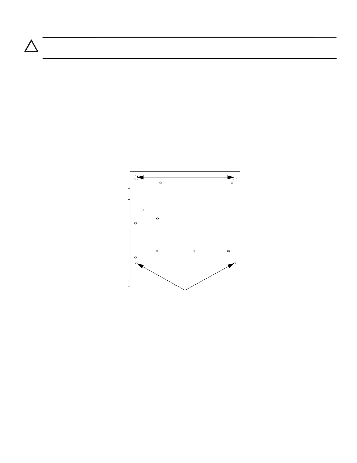
1. Mark and pre-drill hole in the wall for the top keyhole mounting bolt using the dimensions illustrated below.
2. Install top fasteners in the wall with the screw head protruding.
3. Place backbox over the top screws, level and secure.
4. Mark and drill the left and right lower mounting holes.
5. Install remaining fasteners and tighten.
4.1.1 Preventing Water Damage
Water damage to the fire system can be caused by moisture entering the cabinet through the conduits. Conduits that are installed to enter the
top of the cabinet are most likely to cause water problems. Installers should take reasonable precautions to prevent water from entering the
cabinet. Water damage is not covered under Warranty.
4.1.2 Removing the IFP-75 Assembly from the Housing
If it should ever be necessary to remove the control panel assembly from the cabinet for repair, do so by removing the screws that hold the
control panel in to the cabinet. Do not attempt to disassemble the circuit boards.
4.1.3 Dead Front Installation and Removal
This section provides instructions to install and or remove the optional dead front for the control panel cabinet.
Installing the Dead Front
Follow these steps to properly install the dead front panel into the control panel cabinet.
1. Remove the top two screws which secure the annunciator to the board. Leave the bottom two screws installed. See Figure 4.2 for
annunciator screw location.
2. Set the dead front into the cabinet.
CAUTION: DISCONNECT POWER
TO AVOID THE RISK OF ELECTRICAL SHOCK AND DAMAGE TO THE UNIT, POWER SHOULD BE OFF AT THE
CONTROL PANEL WHILE INSTALLING OR SERVICING.
11.25”
Figure 4.1 IFP-75 Cabinet
lower mounting holes
 Loading...


