52 IFP-75 Series Manual — P/N LS10147-001SK-E:E 4/6/2022
Control Panel Installation Remote Station Applications
• Max Voltage: 27.4VDC
• The maximum coil and wire resistance (combined) must not exceed 30 ohms.
To install the 5220 for city box connection:
1. Use one of the knockouts on the right side of the control panel to connect the 5220 using a short piece of conduit (must not exceed 20
feet in length).
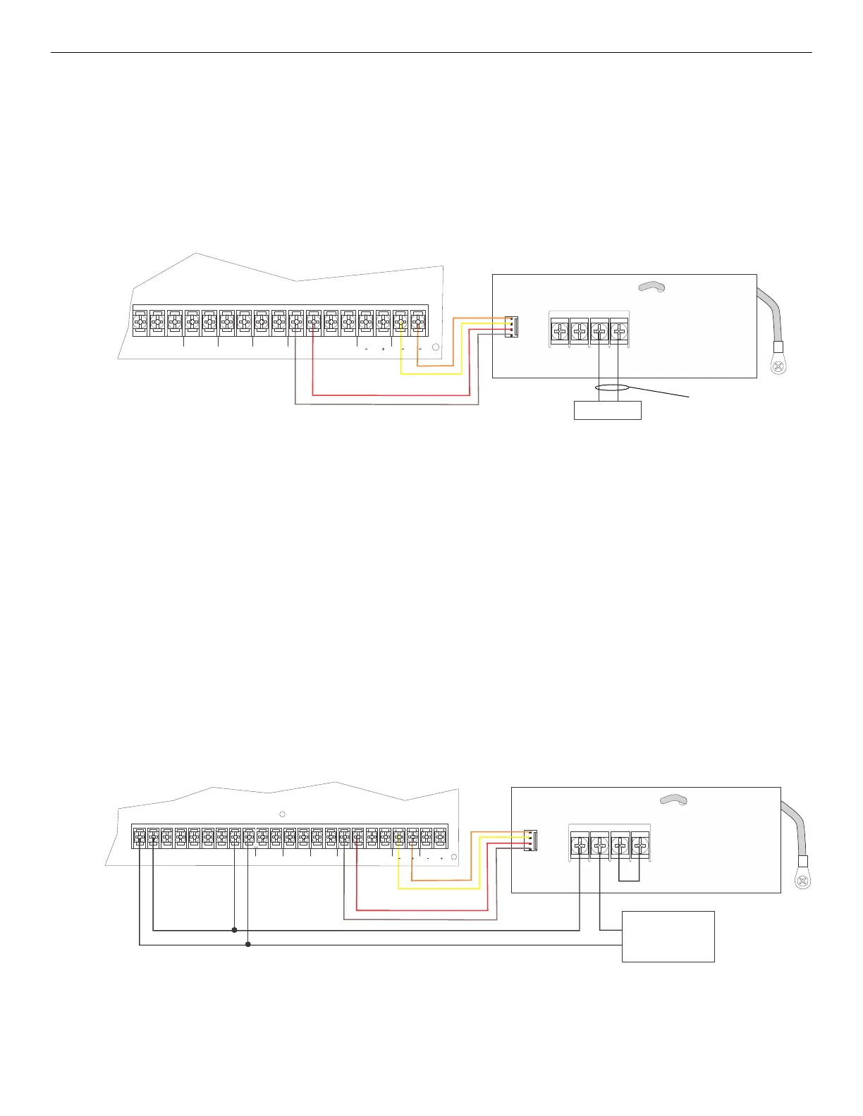
2. Wire the 5220 to the control panel as shown in Figure 4.45. This drawing also shows how to connect the city box coil to terminals 3 and
4 on the 5220. Do not install an EOL resistor in the terminals of the NAC circuit used for this application.
3. Connect earth ground wire to the 5220 chassis with mounting screw.
4. Program the NAC circuit used as a continuous and non-silencing. Refer to Section 8.5 for point programming, Section 8.4 for group
settings, and Section 8.3 for zone settings and mapping.
It is not possible to reset the remote indication until you clear the condition and reset the control panel.
4.18.3 NFPA 72 Polarity Reversal
Using the 5220 Module
When the 5220 is wired and programmed for polarity reversal, it reports alarm and trouble events to a remote site. Alarms will override trou-
ble conditions and it will not be possible to reset the remote indicator until the condition is cleared and the control panel is reset.
If an alarm condition occurs, the alarm relay will close, overriding the trouble condition.
• Standby Current: 100mA
• Alarm: 100mA
• Max. Voltage: 27.4VDC
To install the 5220 for polarity reversal, follow the steps below:
1. Locate the knockout on the right side of the control panel cabinet to connect the 5220 using a short piece of conduit (must not exceed 20
feet in length).
2. Wire the 5220 to the control panel using the four-wire pigtail provided as shown in Figure 4.46. This diagram also shows how to
connect the 5220 to the remote indicator. Do not install an EOL resistor in the terminals of the NAC circuit used for this application.
3. Connect earth ground wire to the 5220 chassis with mounting screw.
4. Program the NAC circuit used as continuous and non-silencing. Refer to Section 8.5 for point programming, Section 8.4 for group
settings, and Section 8.3 for zone settings and mapping.
5. If necessary, adjust loop current using the potentiometer (R10) on the 5220 board. Normal loop current is 2-8 mA with a 1k ohm remote
station receiving unit. Maximum loop resistance is 3k ohms.
NO NC C
TROUBLE
SLC IN
+
_
SLC OUT SLC PROG
+
_
+
_
SBUS
A
B
+
_
NAC 1
NAC 2
NAC circuit 2 used as an example.
Either NAC circuit can be used.
non-supervised,
non-power-limited
city box
Figure 4.45 City Box Connection
orange
yellow
red
brown
14
NO NC C
TROUBLE
RELAY
2
C NO NC
RELAY
1
C NO NC
SLCIN
+
_
SLCOUT
SLCPROG
+
_
+
_
SBUS
A
B
+
_
NAC 1
NAC 2
+
-
All circuits power-limited
All wiring supervised.
Jumper terminals
3 & 4 when City
Box is not used.
remote
indicator
Program relay
for alarm.
orange
yellow
red
brown
NAC circuit 1 and Relay 2 used as examples.
Either NAC and relay circuit can be used.
Not suitable for remote station protected premises service where separate transmission
circuits are required for fire supervisory (if applicable) and trouble signals.
Figure 4.46 Polarity Reversal Connection Using the 5220 Module
 Loading...


