MC Toolkit Software with Honeywell HART Transmitters
Release 3 34-ST-25-20 MC Toolkit User Manual 45
9/06
Honeywell HART Main Menu Procedures
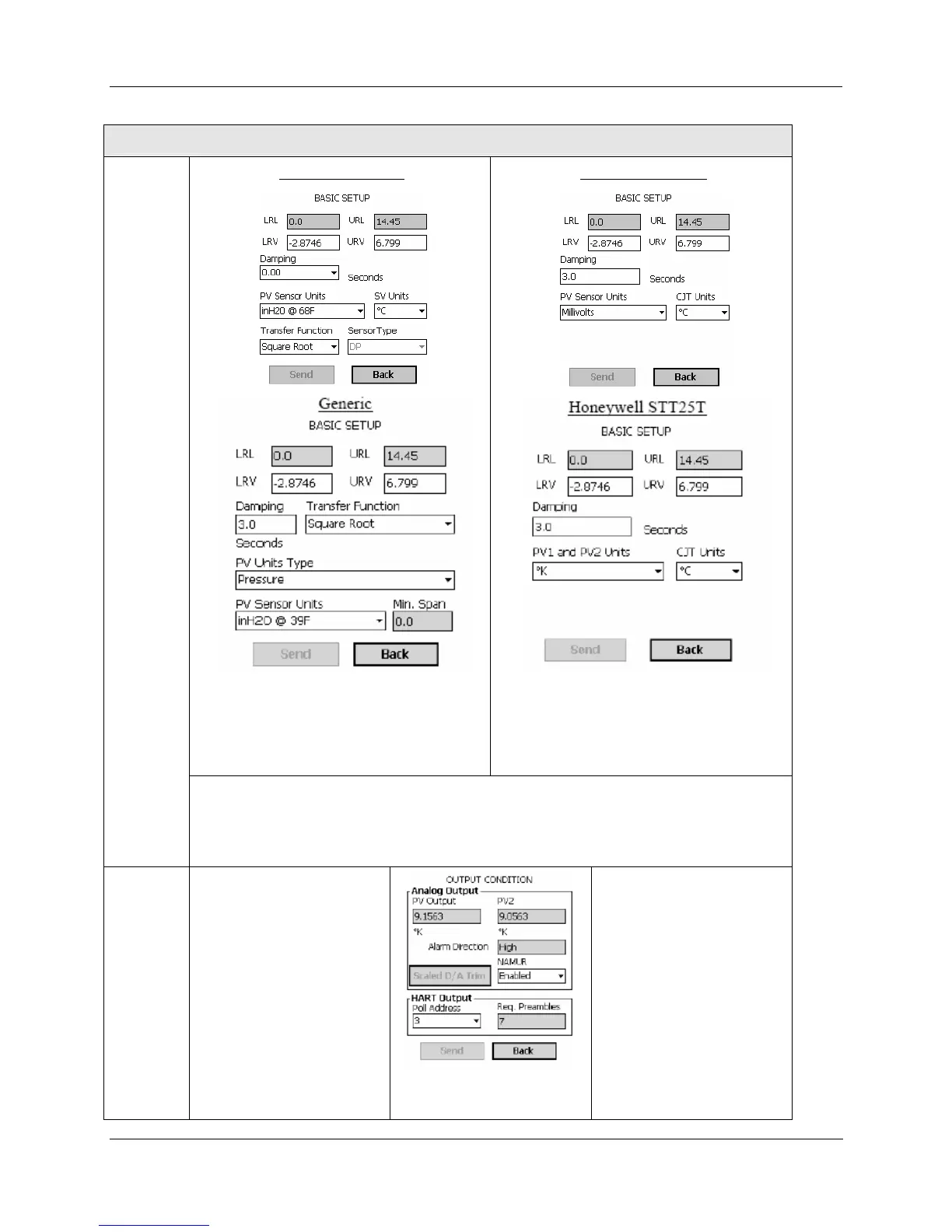
Basic
Setup
Honeywell ST 3000
Transfer Function - Linear or Square Root
(select)
SV Units - Engineering Units for
Secondary Variable (select)
Honeywell STT25H
CJT Units - Engineering Units for Cold
Junction Temperature (select)
PV1 and PV2 Sensor Units (r/w) -
Engineering Units
LRL - Lower Range Limit; URL - Upper Range Limit (read)
LRV - Lower Range Value ; URV - Upper Range Value (enter or read)
PV Sensor Units (r/w) - Engineering Units (select)
Damping - Filtering factor for process "noise" (in seconds - select)
Output
Condition
PV Output (r)
PV2 (r) (STT25T Only)
Alarm Direction - Failsafe
(
Upscale | Downscale)
jumpered or switched in
field
device)
Scaled D/A Trim - (Refer to
Table 16 for more
information.)
NAMUR (STT25H,
STT25T)– Select output
levels:
Standard or NAMUR
HART Output
Poll Address
To change the Poll Address
(0-15) of the connected
device:
• Select the desired address
from the pull-down list
• Select the
Send button.
Req. Preambles - Number
of preambles required