40
www.honeywell.com
Page 40
Mini-AT User Guide
Jumpers JB29, JB30, and JB31 must be set correctly in order for the Mini-AT to provide a single Form-C
pulse output. Figure 9 will assist with locating these jumpers on the main board.
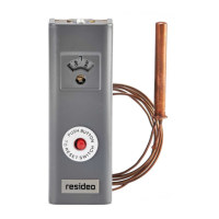
1) Install shorting jumpers (40-2467) at JB29 pins 2-3 and 6- 7
2) Install two (2) six position shorting jumpers at JB30 so that all six pins on the top row of pins are shorted
together and all six pins on the bottom row are shorted together of pins JB30.
3) Install a shorting jumper at JB31 pin 2-3.
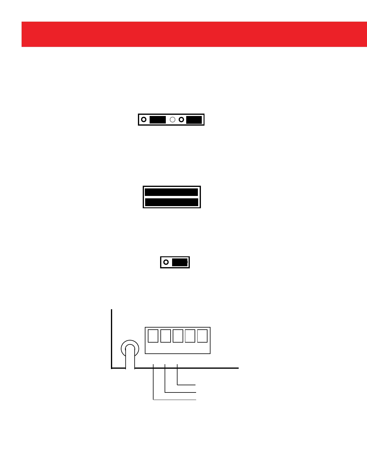
4) Connect wiring as shown below.
Note: Pulse width for Form C pulses can be adjusted by changing Item Code 115 using MasterLink32 or
Mini-AT Link software.
1 3 5 7 9 11
2 4 6 8 10 12
JB30
JB31
1 2 3
JB29
1 2 3 4 5 6 7
K Y
Z
A- A+
TB 1
Normally Closed
Common
Normally Open
 Loading...