41
Page 41
Mini-AT User Guide
Output Pulse Specifications
1. All outputs are isolated from ground and each other.
2. Outputs are rated for
DC only, from 3.0 volts to 30.0 volts.
Observe polarity.
3. The corrected volume pulser circuits will sink up to
15 milliamperes (DC) for Form-C outputs and up to 5
milliamperes (DC) for Form-A outputs.
4. The electronic Form-C volume output counts consist of contact
closures between both the K- Y and the K-Z terminals. For
proper counting, the receiving device must count both.
The pulse-off time for Form-A pulses can be varied by the selection of item 115. If the board jumpers are
configured for Form-C, then Item Code 115 controls the pulse width of the Form-C pulses.
Select: 0 - 0.0625 Sec.------Default
1 - 0.5000 Sec.
2 - 1.0000 Sec.
3 - 0.1250 Sec.
4 - 0.2500 Sec.
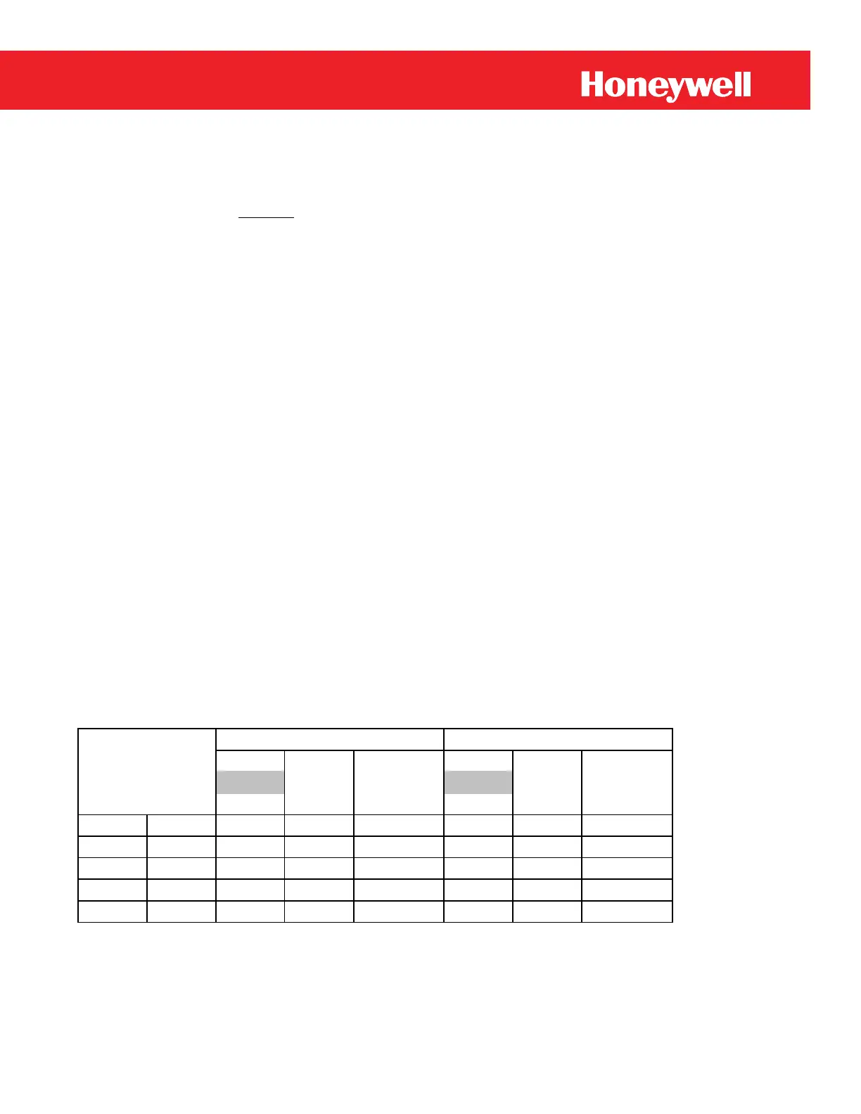
Table 5
Output Pulse Codes
The pulse timing chart on the next page compares the relationship of Pulse Width, Pulse Cycle, Pulse Off Time
and Pulse Repetition Rate.
Pulse Pulse
Width Off
Sec. Sec.
0 0.0625 0.0625 0.0625 16 0.0625 0.125 8
1 0.5 0.5 0.5 2 0.9375 1 1
2 1 1 1 1 1.9375 2 0.5
3 0.125 0.125 0.125 8 0.1875 0.25 4
4 0.25 0.25 0.25 4 0.4375 0.5 2
Form A
Code (Sec)
Pulse
Repetition
Rate, CPS
Pulse
Repetition
Rate, CPS
Pulse
Cycle
Sec.
Pulse
Cycle
Sec.
Form C
 Loading...