Chapter 3 - Plan and Install MLPLC
5. Wiring
l The I/O must be wired using high-voltage cables or power cables. Lower-voltage wires can
cause inductive disturbance that may result in abnormalities or failure of the PLC operation.
l Ensure that the cables do not pass in front of the I/O operation indicator (LED), as it may obstruct
the indicator.
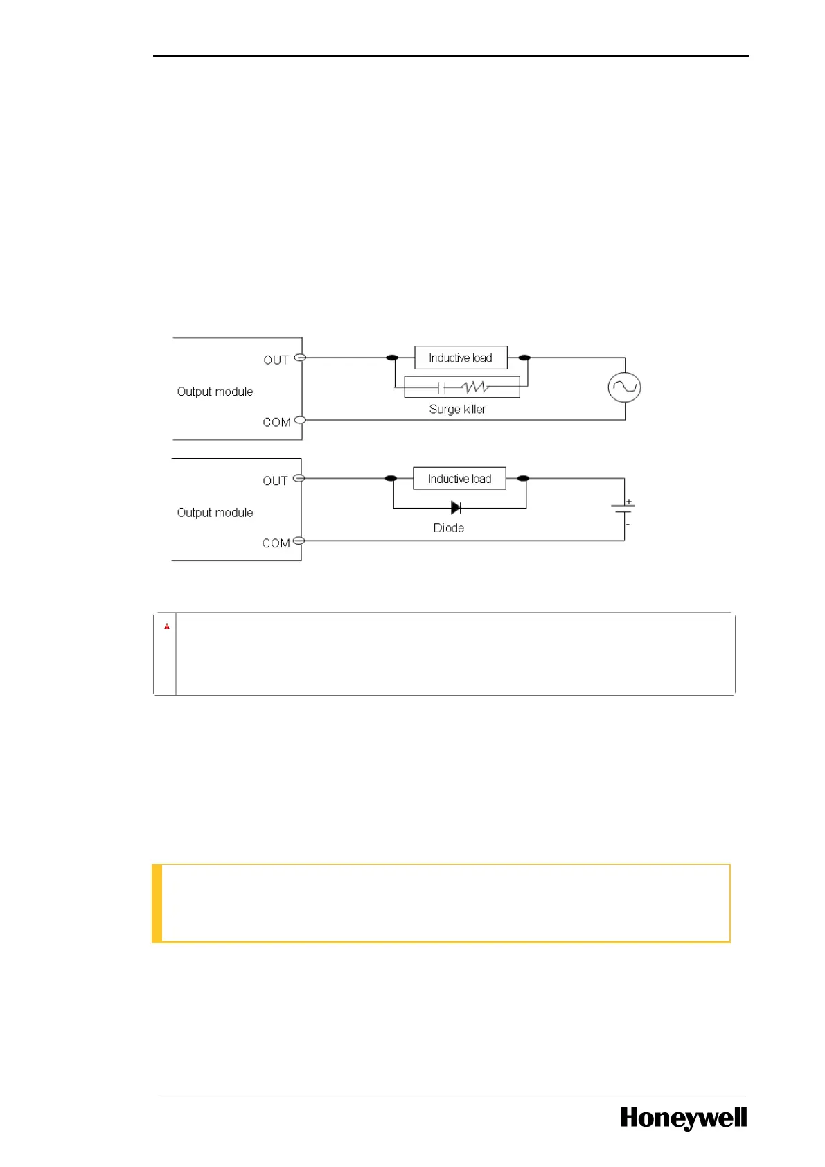
l When inductive load is connected to output module, connect a surge absorber or diode, parallel
to the load.
The following image illustrates the terminal block wiring.
Figure 10: Terminal block wiring
WARNING
Do not apply excessive pressure on the I/O module or separate the PCB board from
the case.
3.2 Mounting Chassis
Cabinet mounting
Inserting a module
ATTENTION
The images in this section are an example for ML200R. Chassis mounting and module mounting
is common for both ML200 IEC and ML200R.
Perform the following steps to insert a module.
- 29 -

 Loading...


