Chapter 1 - Masterlogic components
The following image illustrates the expansion base of ML200R, which supports dual I/O link
redundancy.
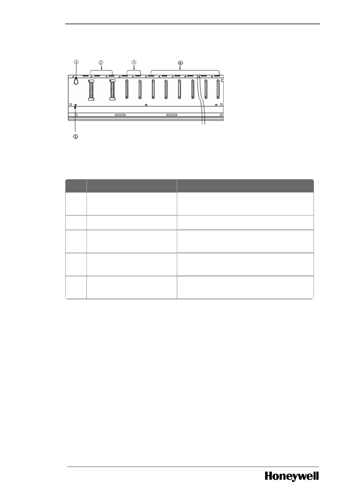
Figure 5: Expansion base of ML200R (with dual I/O link redundancy)
The following table provides the expansion base details of ML200R, with dual I/O link redundancy.
Table 18: Expansion base details of ML200R
Index Part Function
1 Base attached guide hole For attaching the main base to the panel in the
control panel.
2 Power module connector For installation of power supply module.
3 Expansion redundancy drive
module connector
For installation of expansion redundancy driver
modules.
4 Module built-in connector For installation of I/O, special and other
communication modules.
5 FG terminal The ground terminal connected to the shielded
pattern of the PCB board.
1.5 Types of cables
Cables for ML200-IEC
Expansion cable connection
The expansion cables contain high frequency noise. Therefore, to meet the CE conformance standards,
attach a ferrite core to the expansion cable as illustrated in the following figure.
- 14 -
 Loading...


