l Both CPU modules must have the same version of the operating system.
l The configuration of both the CPU modules must be in the same sequence. For example: If
2MLL-EFMT is installed in the slot 0 of CPU-A, 2MLL-EFMT in the CPU-B must be installed
in the slot 0.
Architecture without dual I/O link redundancy
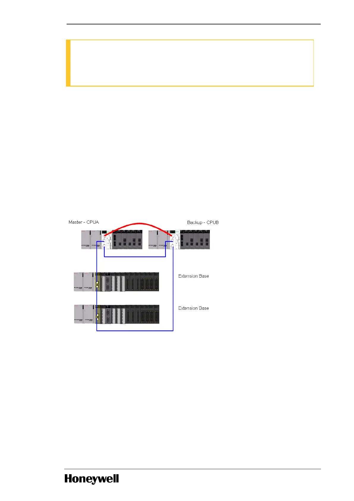
The cable connection for ML200R without dual I/O link redundancy is as follows:
l Connect the synchronization cable between Master and Standby CPUs
l Synchronization cable: Tx to Rx, Rx to Tx (Multi-mode FO, LC connector type)
l Connect the expansion cable between I/O racks and CPUs in a Ring Configuration
l UTP cable: Direct or Cross cable (Cross cable is recommended)
l Fiber Optic cable: Tx to Rx, Rx to Tx (Multi-mode FO, LC connector type)
The following image illustrates the ML 200R architecture without dual I/O link redundancy.
Figure 15: ML200R architecture without dual I/O link redundancy
Architecture with dual I/O link redundancy
The cable connection for ML200R with dual I/O link redundancy and is as follows:
l Connect the synchronization cable between Master and Standby CPUs
l Synchronization cable : Tx to Rx, Rx to Tx (Multi-mode FO, LC connector type)
l Connect the expansion cable between I/O racks and CPUs in a Ring Configuration
l UTP cable : Direct or Cross cable (Cross cable is recommended)
- 38 -
Chapter 3 - Plan and Install MLPLC

 Loading...


