Chapter 3 - Plan and Install MLPLC
4. AC 110V/AC 220V/DC 24V cables must be properly twisted and connected with the shortest
distance.
5. AC 110V/AC 220V cable must be as thick as possible (2mm
2
), to reduce the voltage drop. AC
110V/ DC 24V cables must not be installed close to the main circuit cable (high voltage/high
current) and I/O signal cable. They must be 100mm away from such cables.
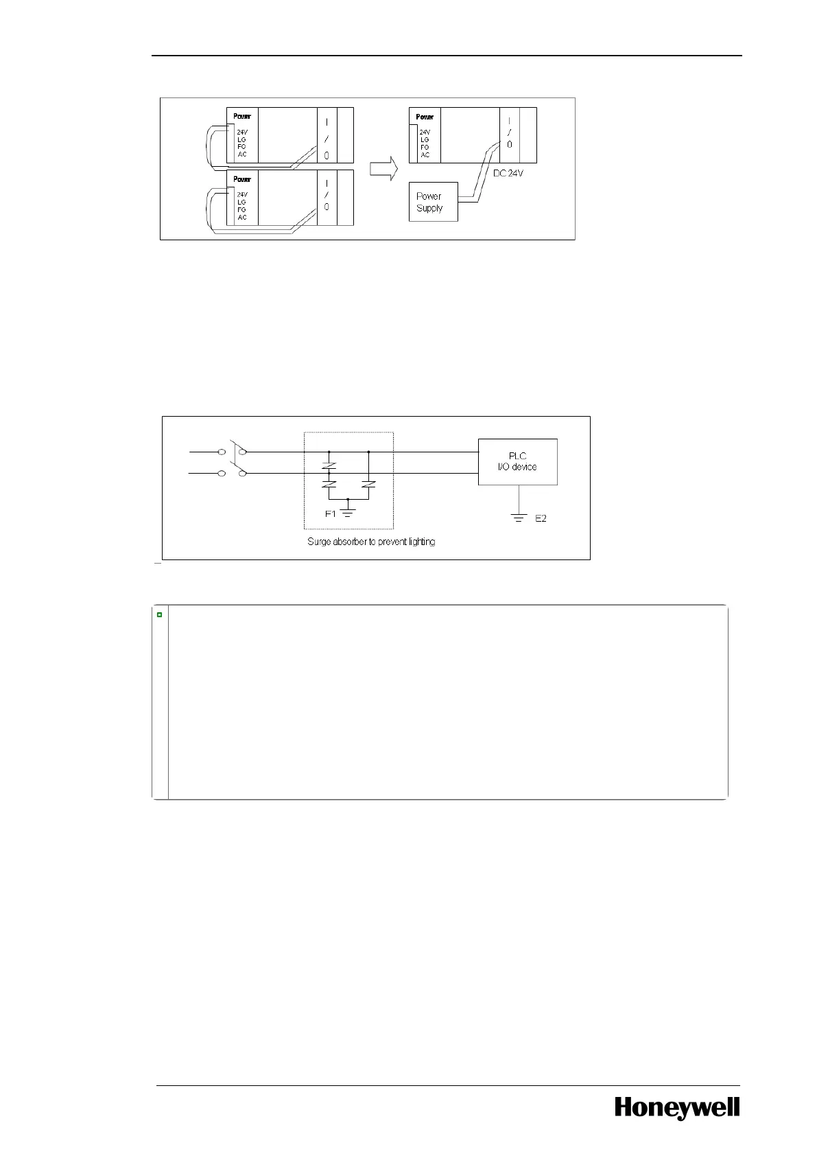
6. Use a surge absorber as a protection against lightning, as displayed in the following figure.
TIP
l Separate PLC earth (E2) from earth (E1) of surge absorber against lightning.
l In case of an increase in voltage, the surge absorber ensures that it does not increase more
than the predefined maximum limit.
l Use a shielded isolation transformer or noise filter in areas where higher noise levels are
expected.
l It is advisable to use twisted cable for input power. Ensure that the shielded transformer or
noise filter wiring does not pass the duct.
Module LEDs
LED indicators for ML200-IEC
The following table describes the LED indicators for ML200-IEC.
Table 25: LED indicators for ML200-IEC
- 45 -

 Loading...


