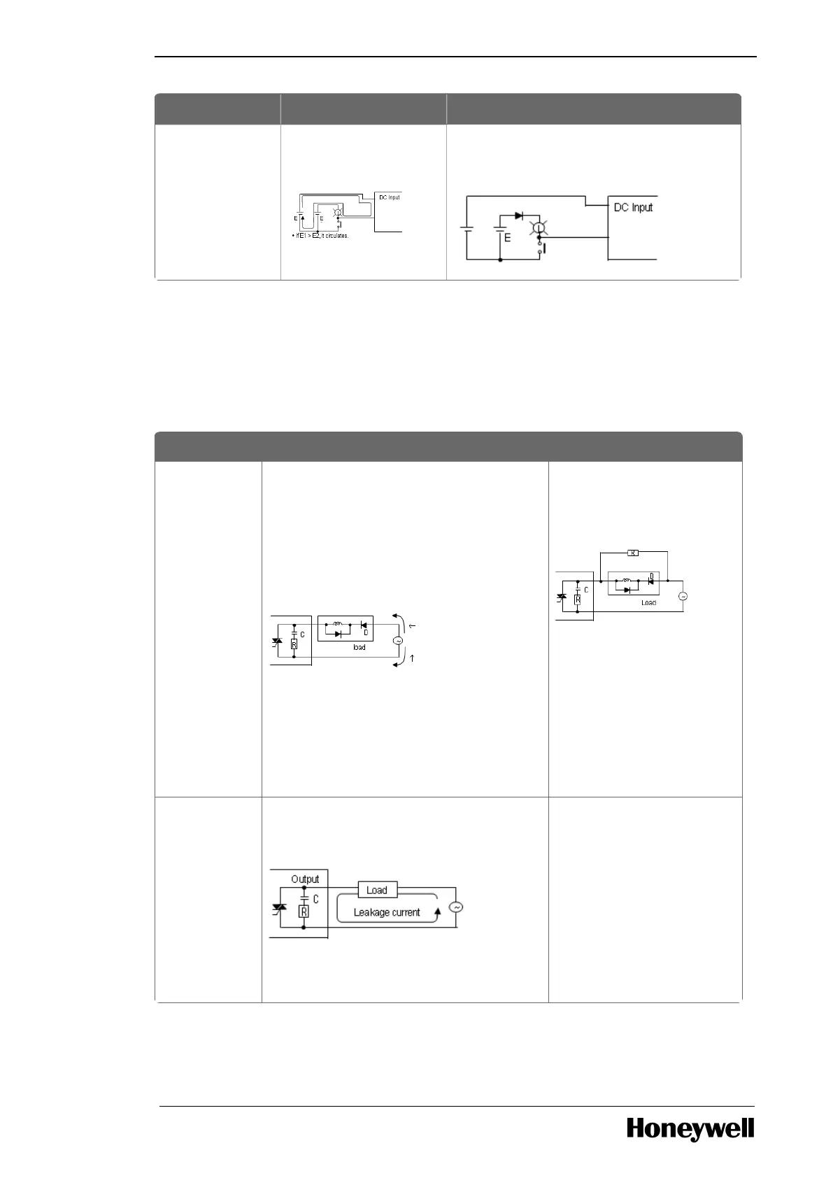
Phenomena Causes Measures
Excessive
voltage is
allowed to
load when
output contact
is off.
l If load contains half-wave rectification
(solenoid valve may have it).
l If the polarity is ←, C is charged while the
voltage + power voltage charged to C is
allowed to both ends of diode (D). When
the polarity is ↑. The maximum voltage is
approximately. 2√2.
Note: While using it as described
previously, the output element does not
have any problem but the performance of
diode (D) in load may be reduced,
probably causing a trouble.
l Connect a dozen ~
several hundreds kΩ
resistor to a load in
parallel.
Load cannot
be off
l Leakage current from surge absorbing
circuit connected to an output element in
parallel.
l
Connect a dozen of kΩ
resistor or C-R of which
impedance is equal to the
resistance to load in
parallel.
Note: If the length of wiring
from output module to load
is long, it may have leakage
current from the capacity of
cables.

 Loading...


