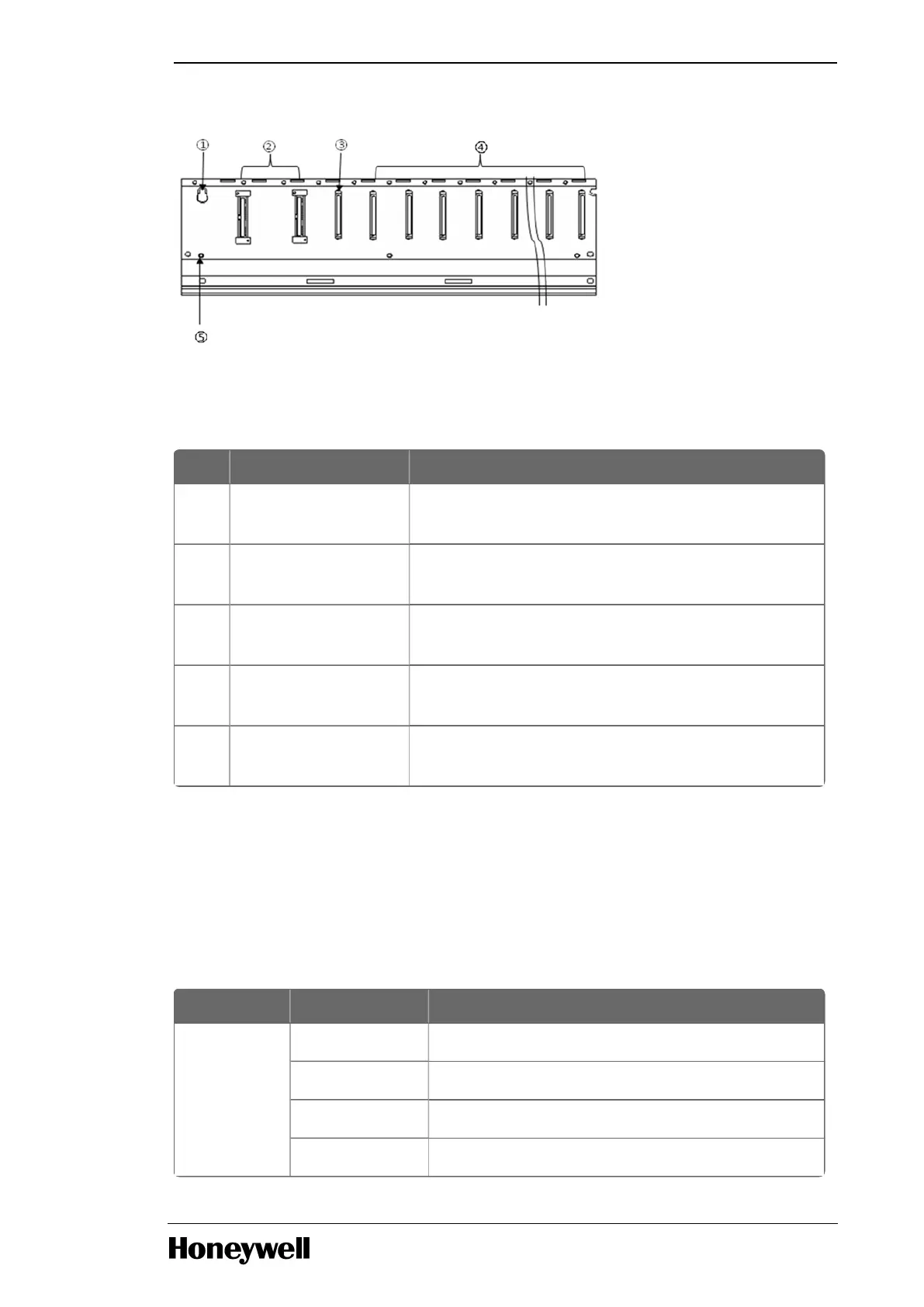
Figure 4: Expansion base of ML200R (without dual I/O link redundancy)
The following table provides the expansion base details of ML200R, without dual I/O link redundancy.
Table 16: Expansion base details of ML200R
Index Part Function
1 Base attached guide
hole
For attaching the main base to the panel in the control
panel.
2 Power module
connector
For installation of power supply module.
3 Expansion driver
module connector
For installation of expansion driver module.
4 Module built-in
connector
For installation of I/O, special and communication
modules other than Ethernet module.
5 FG terminal The ground terminal connected to the shielded pattern
of the PCB board.
Expansion base with dual IO link redundancy
The expansion base of ML200R consists of the power module, expansion driver module, I/O module,
special module, and the communication module. (Ethernet module is not allowed in the expansion
base).
The following table provides details about the expansion base and expansion driver module for
ML200R (with dual IO link redundancy).
Table 17: Expansion base and expansion driver module for ML200R
PLC Types Part Number Description
ML200R 2MLR-E12H Expansion redundancy Base 12 slot
2MLR-DBDF Expansion redundancy Driver module FO
2MLR-DBDT Expansion redundancy Driver module TP
2MLR-DBDH Expansion redundancy Driver module TP/FO
- 13 -
Chapter 1 - Masterlogic components
 Loading...


