Chapter 3 - Plan and Install MLPLC
Item ML200R Comprises of
of I/O
Address in
main base
points) is assigned to main base and main base has station number of 0.
ATTENTION
l The base has its base number as ‘0’ and the expansion base has a switch to set the base
number.
l The CPU module is only allowed in the main base and two slots are required for the CPU
module.
l The module starts operating after the module type and I/O parameter are set using
SoftMaster and the correct module type is mounted on the base.
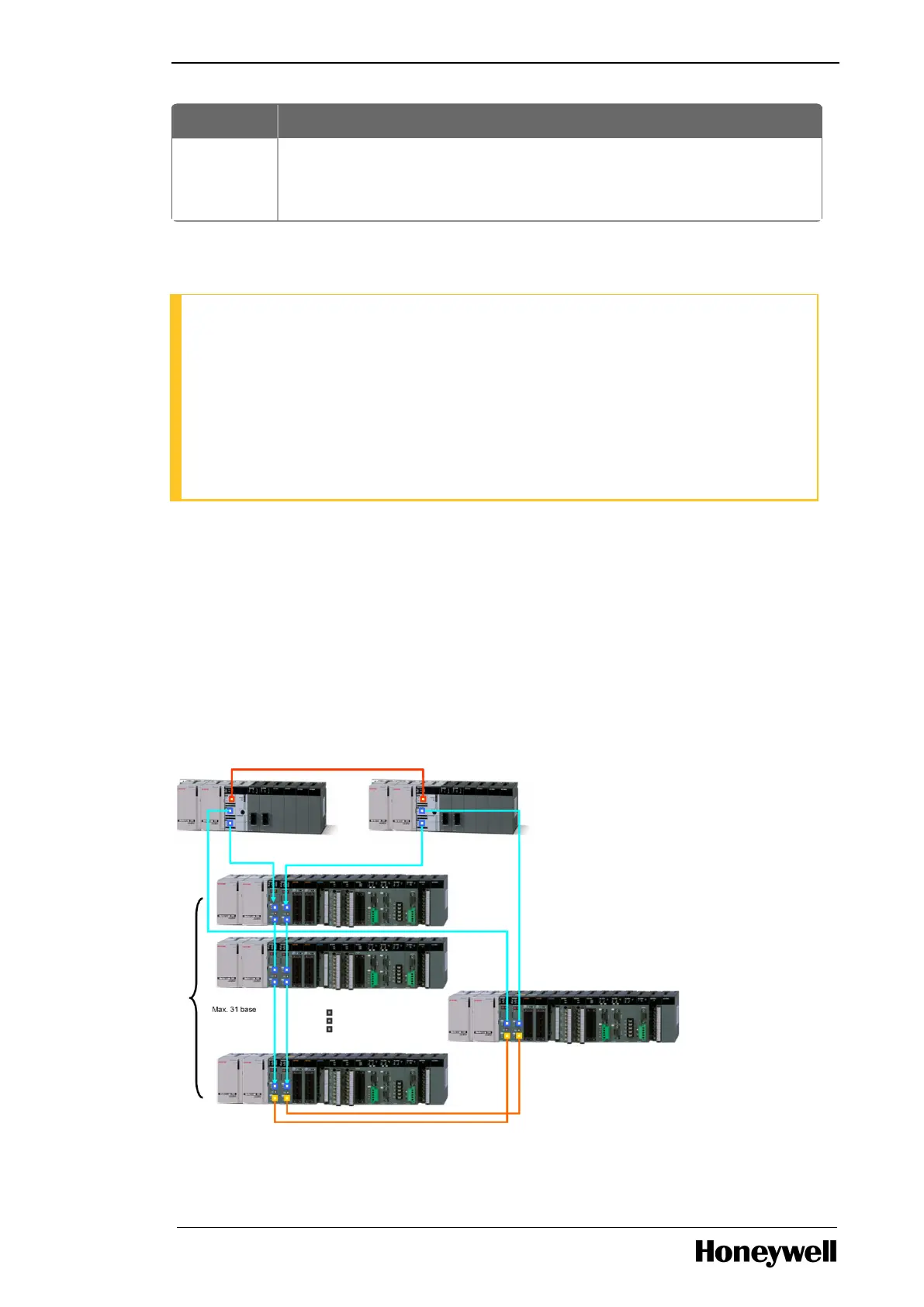
Example of mixed topology (combination of electric and optic fiber)
ML200R with dual I/O link redundancy using mixed modules.
In a system, the optical modules can be used in the following two cases. This helps to build an
optical/electrical mixed module network without an additional converter.
l When the distance between electrically established stations is more.
l Electrical noise is severe.
2MLR-CPUH/T for both CPUs and 2MLR-DBDT and 2MLR-DBDH for expansion drive module.
- 41 -

 Loading...


