Item ML200R Comprises of
Main Base Two main base with identical module
Maximum
Expansion
Base
31 Expansion bases
Max. I/O
modules
Up to 372 (31 X 12) I/O modules (Up to 372 (31 X 12) I/O modules can
be installed in expansion base.)
Maximum
I/O point
16 points module : 5952 points
32 points module : 11904 points
64 points module : 23808 points
Maximum
distance
between
nodes
Fiber Optic : 2km
Twisted pair cable : 100m
l Total max length
l Optical multi mode: 62km (when installing 31 expansion
modules)
l Optical single mode: 465km (when installing 31 expansion
modules)
l Electrical: 3.1km (when installing 31 expansion modules)
Allocation
of I/O
Address in
Expansion
base
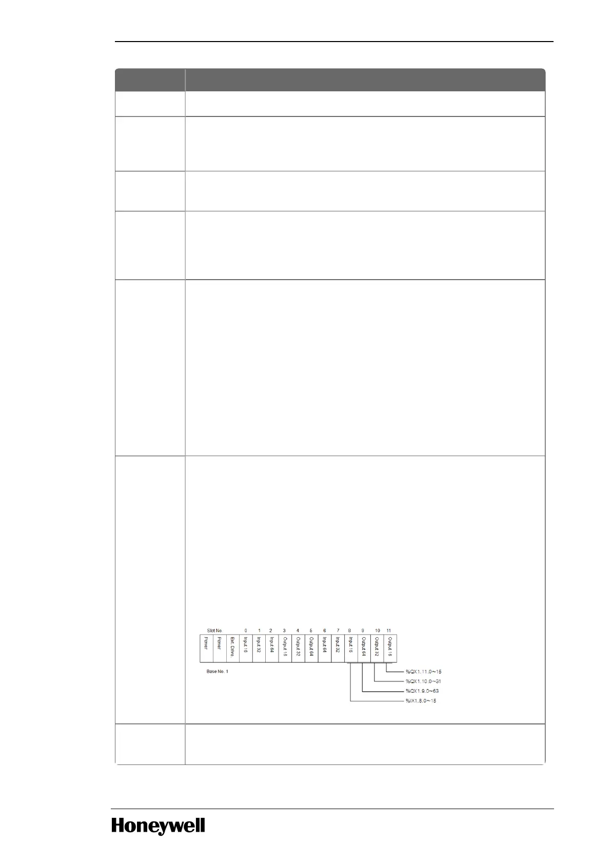
Start address of input and output point is determined by the station
number set in the expansion driver module.
Each slot of the base is allocated 64 points (fixed), irrespective of the
type of module mounted.
Special modules can be mounted in any position. Unlike digital I/O
modules, a special module is not allocated to any I/O address. A special
module is controlled by a dedicated function block and the address is
automatically allocated to the memory.
For instance, the I/O number of 12 slot base is allocated as follows:
Allocation Only communication module is allowed in the main base. Hence, I/O
addressing is not required. However, same number of points (that is, 768

 Loading...


