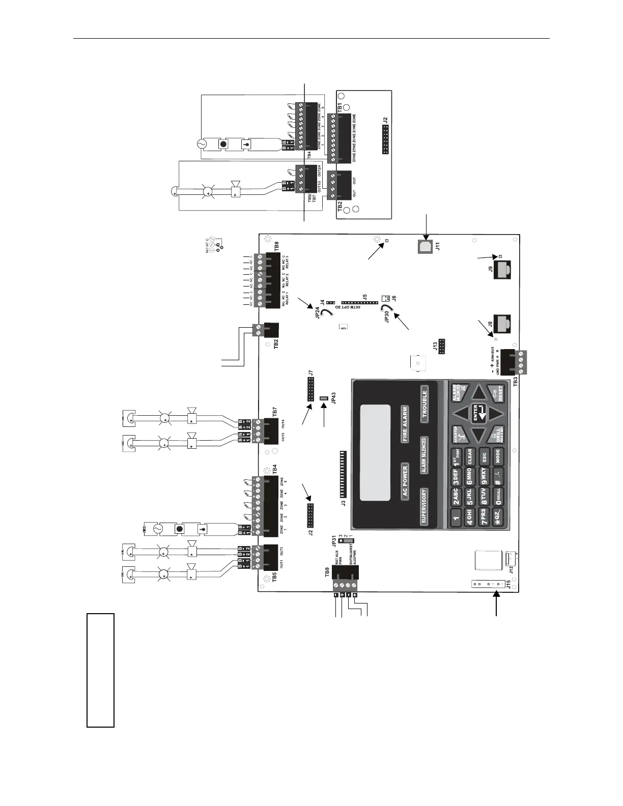
Dummy load all unused circuits
with 4.7K, ½ watt End-of-Line
resistors
Style Z (Class A) NAC
Style D (Class A) IDC
Class A Converter Module
3 Programmable Relays
Nonsupervised relay contacts
Contact Ratings
2.0 amps @ 30 VDC (resistive)
0.5 amp @ 30 VAC (resistive)
Contacts shown below in normal
condition (AC power with no alarm,
trouble, or supervisory activity)
A Fail Safe Trouble relay switches
to the NC position during trouble
conditions and under loss of all
power.
(*Factory default relay
programming)
Alarm*
Trouble*
Supervisory*
Remote
Synchronization
Output (see note 2)
Special Application
Power
24 VDC filtered,
supervised, and power-
limited. 0.040 amp
maximum. Requires
4.7K ohm ELR.
Notes:
1. SFP-5UD/E = 2.5 amps max. per NAC
SFP-5UDC= 3 amps max. per NAC
2. Remote Sync Output is required only for
the SFP-5UD/E: Refer to “Remote
Synchronization Output” on page 34.
3. 18 Amp Hour max. for SFP-5UD/E
26 Amp Hour max. for SFP-5UDC
Class A Converter Module
Remove jumper JP43 to
disable Ground Fault
Detection circuit (only with
approval of AHJ)
Cut this jumper to supervise
the 4XTM module when
installed (see J4 & J5)
Cut this jumper to
enable Supervisory
Relay when 4XTM
module is installed
Auxiliary
Trouble Input
Kiss-off LED
Secondary Phone
Active LED
Primary Phone
Active LED
Primary
Secondary
ANN-SEC
option card connector
USB port for local programming using a
personal computer and PK-5X Utility
DACT Phone Line Jacks
Nonpower-Limited
Battery (see note 3)
24 VDC, supervised,
nonpower-limited
Basic System Connections
5-Zone Panel
Power Supply Connector
For more specific UL wiring
information, refer to page 35.
Important! Removing Ground Fault Disable
Jumper JP43 voids UL/NFPA Style/Class
indentifications for circuits. Remove jumper
JP43 only with the approval of the local AHJ
(Authority Having Jurisdiction).
Special Application
DC Power Outputs 24 VDC)
Nonsupervised, power-limited circuits
Supervise with a power supervision relay
EOLR-1
Resettable Power - 24 VDC filtered,
power-limited (0.5 amp maximum) to
smoke detectors (IDC). Supervision
required.
Nonresettable or Resettable Power
Jumper selectable by JP31, 24 VDC
filtered, power-limited (0.5 amp maximum).
Supervision required. Nonresettable
Power suitable for powering smoke
detectors.
Configure TB9, Terminals 1 & 2 as
Resettable or Nonresettable Power.
• Resettable Power - jumper JP31 pins 2
& 3
• Nonresettable Power - jumper JP31 pins
1 & 2 (as shown)
4
3
2
1
{
{
Notification Appliance Circuits (see note 1)
Special Application Power
NAC #1, #2, #3, & #4, Style Y (Class B) (Supervised, Power-
Limited) (See Style Z illustrated near right edge of board.)
4.7Kohm, ½ watt End-of-Line Resistor
PN 71252
NAC #1 NAC #2 NAC #3 NAC #4
Special Application
Power
IDCs 1 through 5, Style B
(Class B) (Supervised,
Power-Limited) (See
Style D illustrated near
right edge of board.)
4.7Kohm, ½ watt End-of-
Line Resistor
PN 71252
Initiating Device Circuits
Push switch down to
upgrade software
ms-5udlayout.wmf

 Loading...


