FireLite SLC Wiring Manual — P/N 51309:P4 9/17/2014 15
Measuring Resistance & Length Wiring Requirements
2.2 Measuring Resistance & Length
2.2.1 Two-Wire SLC - Style 4 (Class B)
Loop Resistance
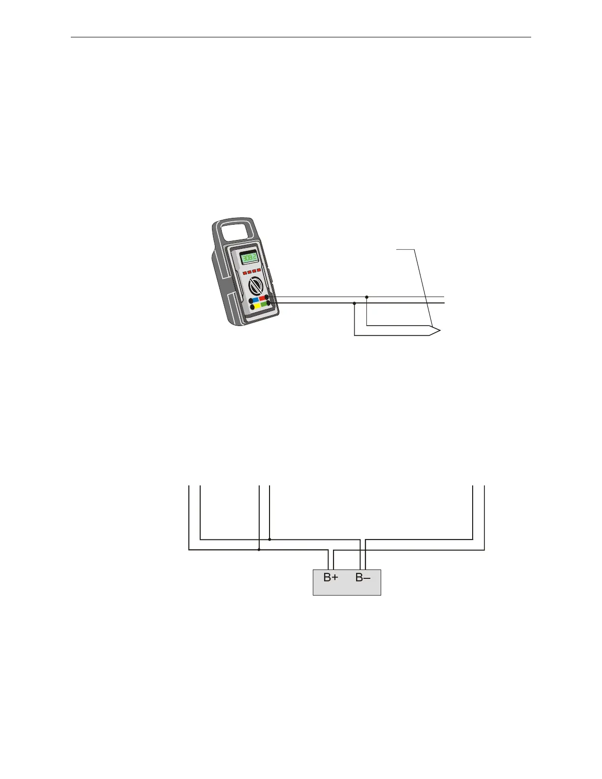
T-tapping of the SLC wiring is permitted for 2-wire Style 4 configurations. The total DC resistance
from the control panel to each branch end cannot exceed 40 ohms. Measure DC resistance as
detailed and shown below:
1. With power removed, short the termination point of one branch at a time and measure the DC
resistance from the beginning of the SLC to the end of that particular branch.
2. Repeat this procedure for all remaining branches in the SLC.
Total Wire Length
The total wire length of all combined branches of one SLC cannot exceed the limits set forth in
each system’s instruction manual. Determine the total length in each SLC by summing the wire
lengths of all branches of one SLC.
In the following figure, the total length of the SLC is determined by adding the lengths of Branch A
plus Branch B plus Branch C.
SLC-meas1.wmf
SLC Out
Branch
Short Point
Figure 2.1 Measuring DC Resistance of a Two-Wire SLC
Branch A Branch B
Branch C
SLC-meas2.wmf
SLC Terminal
Block
Figure 2.2 Measuring the Total Wire Length - Two-Wire SLC
 Loading...