16 FireLite SLC Wiring Manual — P/N 51309:P4 9/17/2014
Wiring Requirements Measuring Resistance & Length
2.2.2 Four-Wire SLC Style 6 & 7 (Class A)
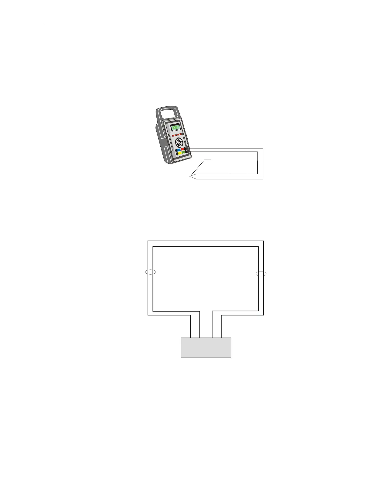
Loop Resistance
The total DC resistance of the SLC pair cannot exceed 40 ohms. Measure DC resistance as detailed
and shown below.
1. Disconnect the SLC channel B (Out) and SLC channel A (Return) at the control panel.
2. Short the two leads of SLC channel A (Return).
3. Measure the resistance across the SLC channel B (Out) leads.
Total Wire Length
The total wire length in a four-wire SLC cannot exceed the limits set forth in each system’s
instruction manual. The figure below identifies the output and return loops from SLC terminal on
the control panel:
SLC-meas3.wmf
SLC Out
SLC Return
Short Point
Figure 2.3 Measuring DC Resistance of a Four-Wire SLC
SLC-meas4.wmf
SLC channel B
(output loop)
SLC channel A
(return loop)
SLC Terminal
Block
Figure 2.4 Measuring the Wire Length – Four-Wire SLC
 Loading...