170
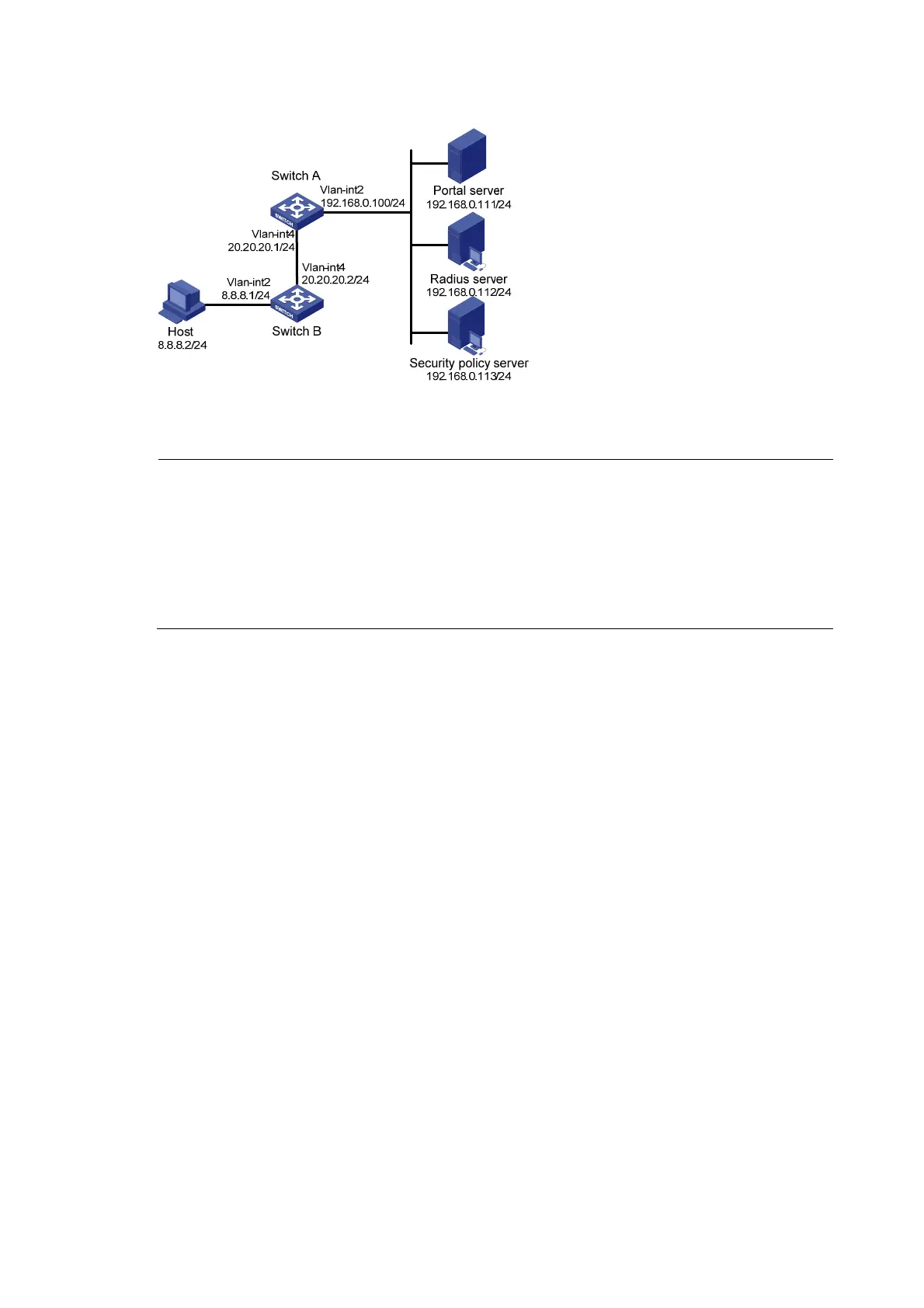
Figure 71 Network diagram
Configuration procedure
NOTE:
• Make sure that the IP address of the portal device added on the portal server is the IP address of the
interface connecting users (20.20.20.1 in this example), and the IP address group associated with the
portal device is the network segment where the users reside (8.8.8.0/24 in this example).
• Configure IP addresses for the host, switches, and servers as shown in Figure 71 and m
ake sure that the
can reach each other.
• Configure the RADIUS server properly to provide authentication and accounting functions for users.
Configure Switch A:
1. Configure a RADIUS scheme
# Create a RADIUS scheme named rs1 and enter its view.
<SwitchA> system-view
[SwitchA] radius scheme rs1
# Set the server type for the RADIUS scheme. When using the iMC server, set the server type to extended.
[SwitchA-radius-rs1] server-type extended
# Specify the primary authentication server and primary accounting server, and configure the keys for
communication with the servers.
[SwitchA-radius-rs1] primary authentication 192.168.0.112
[SwitchA-radius-rs1] primary accounting 192.168.0.112
[SwitchA-radius-rs1] key accounting radius
[SwitchA-radius-rs1] key authentication radius
[SwitchA-radius-rs1] user-name-format without-domain
# Configure the IP address of the security policy server.
[SwitchA-radius-rs1] security-policy-server 192.168.0.113
[SwitchA-radius-rs1] quit
2. Configure an authentication domain
# Create an ISP domain named dm1 and enter its view.
[SwitchA] domain dm1

 Loading...


