180
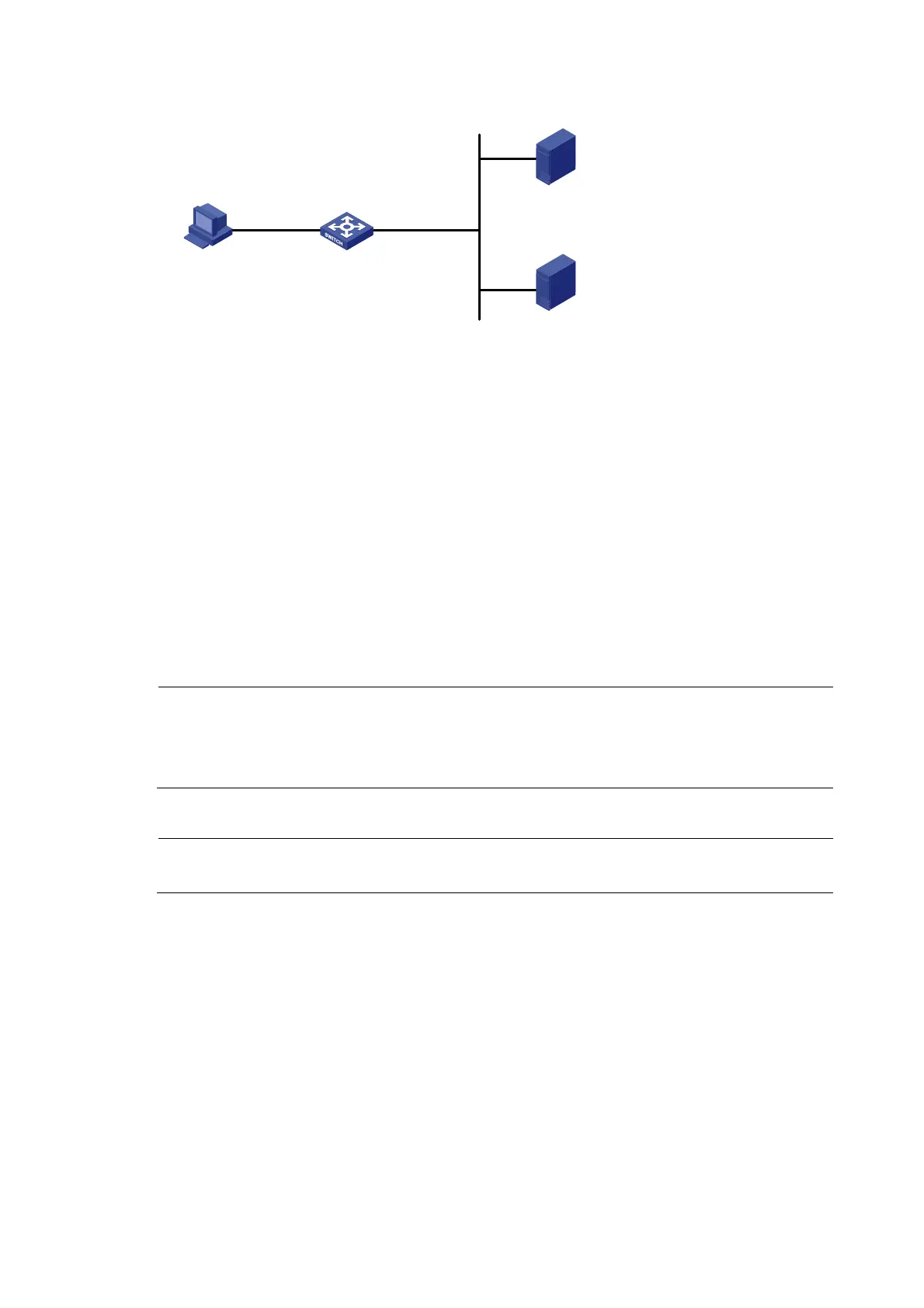
Figure 78 Network diagram
RADIUS server
Switch
Host
2.2.2.2/24
Gateway:2.2.2.1/24
Vlan-int100
2.2.2.1/24
Vlan-int2
192.168.0.100/24
Portal server
192.168.0.111/24
192.168.0.112/24
Configuration considerations
1. Configure the portal server and enable portal server heartbeat function and the portal user
heartbeat function.
2. Configure the RADIUS server to implement authentication and accounting.
3. Configure direct portal authentication on interface VLAN-interface 100, which is connected with
the user host.
4. Configure the portal server detection function on the access device, so that the access device can
detect the status of the portal server by cooperating with the portal server heartbeat function.
5. Configure the portal user information synchronization function, so that the access device can
synchronize portal user information with the portal server by cooperating with the portal user
heartbeat function.
Configuration procedure
NOTE:
• Configure IP addresses for the host, switch, and servers as shown in Figure 78 and m
ake sure that they
can reach each other.
• Configure the RADIUS server properly to provide authentication and accounting functions for users.
1. Configure the portal server (iMC PLAT 5.0)
NOTE:
This example assumes that the portal server runs iMC PLAT 5.0(E0101) and iMC UAM 5.0(E0101).
# Configure the portal server.
Log in to the iMC management platform and select the Service tab. Then, select User Access Manager >
Portal Service Management > Server from the navigation tree to enter the portal server configuration
page, as shown in Figure 79.
• C
o
nfigure the portal server heartbeat interval and user heartbeat interval.
• Use the default value for other parameters.

 Loading...


