Front I/O and power switch assembly
1. Prepare the computer for disassembly (Preparation for disassembly on page 14).
2. Remove the computer access panel (Access panel on page 15).
3. Remove the front bezel (Front bezel on page 16).
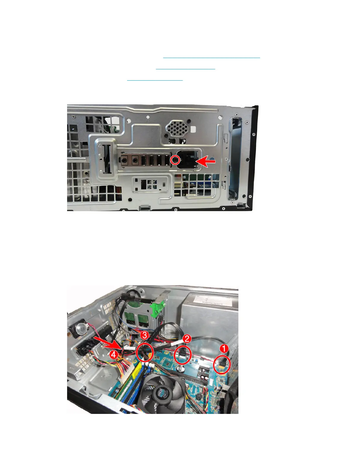
4. Remove the Torx T15 screw that secures the assembly to the chassis, push the tab on the right side of
the assembly to disengage it from the chassis.
5. Remove the cables from the clips on the base pan.
6. Disconnect the three cables from the following system board connectors:
(1) F_AUDIO (yellow)
(2) F_USB1 (white)
(3) F_PANEL (black)
7. Push the assembly into the chassis (4), and then remove the assembly from the inside of the computer.
To reinstall the assembly, reverse the removal procedure.
34 Chapter 4 Removal and replacement procedures – Microtower (MT) chassis