Chapter 4 Retrofitting Options
To Retrofit A5 DC Power Input Assembly (Option 002)
Assembly-Level Service Guide 4-9
4
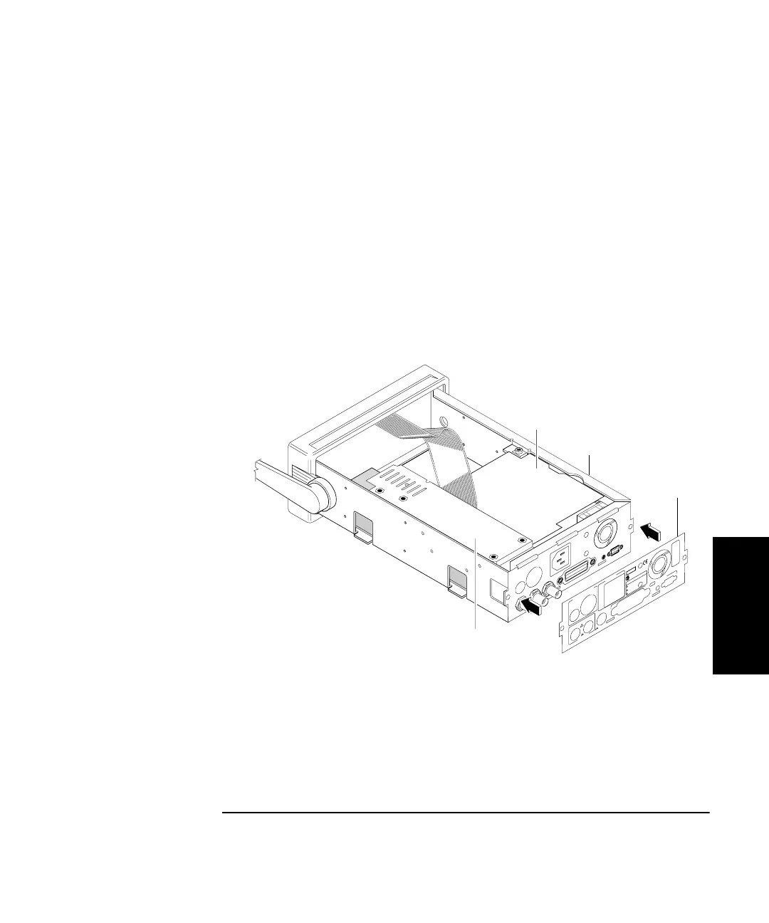
b. Position A5 Power Input Assembly against the rear of the
chassis and align it with the two appropriate holes in the rear
of the chassis.
c. Using the four TORX 10 screws (H2), secure A5 DC Power
Input Assembly to the side of the chassis (MP10) as shown in
Figure 4-1C.
11 To install the rear label (MP11), remove the protective seal from
the back of it and press into place making sure to properly align
the label with the holes in the rear of chassis as shown in
Figure 4-1D.
Figure 4-1D. DC Power Input Assembly Retrofitting
12 Re-install the cover by performing the cover removal procedure,
in Chapter 3 of this guide, in reverse.
Ext Arm
Ref In
!
AC LINE:
10 MHz Out
60 VA
100 - 120 VAC
200 - 240 VAC
50/60/400 Hz
50/60 Hz
OPTIONS
001 MS Oven
010 HS Oven
SERIAL PLATE
To Configure:
Hold Recall during turn-on.
Osc Adjust
RS - 232
ISM 1-A
92
FOR LABORATORY USE BY
QUALIFIED PERSONNEL
FOUR USAGE EN LABORATOIRE
PAR PERSONNEL QUALIFIE
012 US Oven
10-32 VDC
DC Fuse
3 A
INPUTS
EXTERNAL DC INPUT
MP11
MP10
A5
A4