EasyManuals Logo

HP 5800-48G User Manual

HP 5800-48G
126 pages
To Next Page IconTo Next Page
To Previous Page IconTo Previous Page
Page #123 background imageLoading...
Page #123 background image
117
Figure 105 Airflow through the chassis
(1) Front panel (2) Front inlet air vents
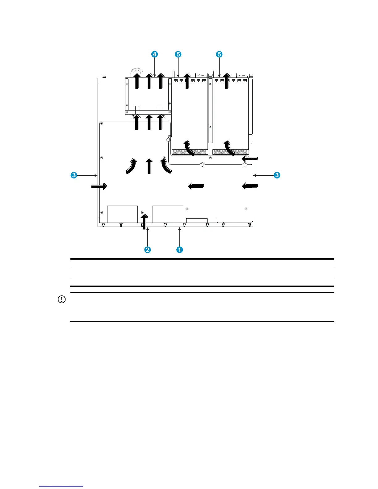
(3) Side inlet air vents (4) Outlet air vents in the fan tray panel
(5) Outlet air vents in the power supply panels
IMPORTANT:
The chassis and the power supplies use separate air aisles. Make sure that both aisles have good
v
entilation.
5820X-14XG-SFP+ (2 slots)/5820X-14XG-SFP+
TAA (2 slots)
The 5820X-14XG-SFP+ (2 slots) and 5820X-14XG-SFP+ TAA (2 slots) switch chassis are 2U high and use
separate air aisles for their upper half and lower half. Make sure that the two air aisles have good
ventilation.
Figure 106
shows the airflow through the lower half of the chassis. Cool air flows in from the left side
of the chassis, circulates through the lower half of the chassis and the power supplies, and exhausts
through the air vents in the fan tray panel and the power supply panels.

Table of Contents

Questions and Answers:

Question and Answer IconNeed help?

Do you have a question about the HP 5800-48G and is the answer not in the manual?

HP 5800-48G Specifications

General IconGeneral
BrandHP
Model5800-48G
CategorySwitch
LanguageEnglish

Related product manuals