68
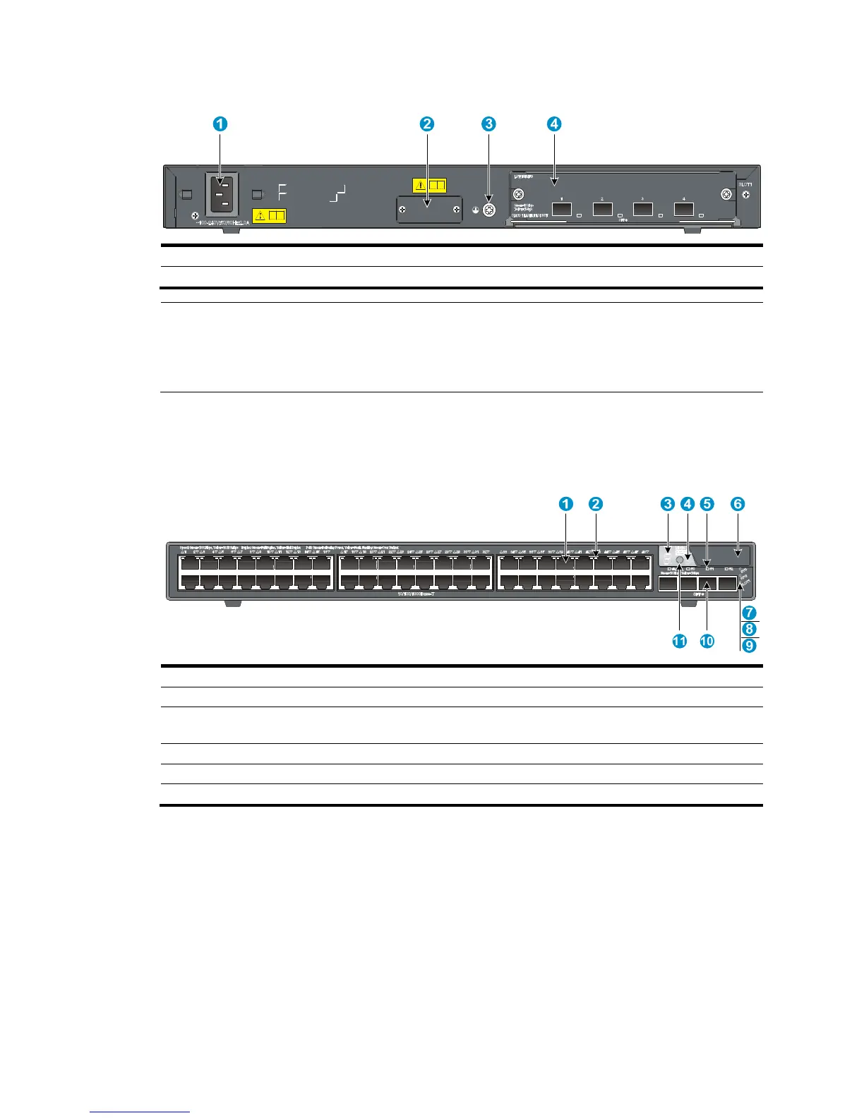
Figure 74 Rear panel
(1) AC-input power
receptacle (2) RPS receptacle
(3) Grounding screw (4) Expansion interface card slot
NOTE:
• The 5800-48G (1 slot) and 5800-48G TAA (1 slot) switches come with the expansion interface card slo
covered by a filler panel. In this figure, an LSW1SP4P0 interface card is installed in the slot.
• These two switches also come with the RPS receptacle covered by a protective cover.
5800-48G-PoE+ (1 slot)/5800-48G-PoE+ TAA (1 slot)
Figure 75 Front panel
(1) 10/100/1000Base-T auto-sensing Ethernet port (2) 10/100/1000Base-T Ethernet port LED
(3) Seven-se
ment LED (4) Port mode LED
(5) SFP+ port LED (6) Logo plate (A console port and a USB port are
under this lo
(7) System status LED (SYS) (8) RPS status LED (RPS)
(9) Interface card status LED (SLOT1)
(11) Port LED mode switchin
To use the console port and USB port, open the logo plate, as shown in Figure 72 and Figure 73.