71
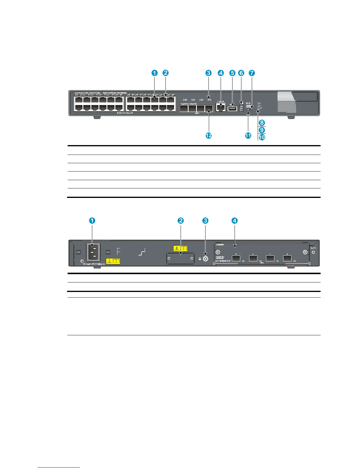
5800-24G/5800-24G TAA
Figure 80 Front panel
(1) 10/100/1000Base-T auto-sensing Ethernet port
(2) 10/100/1000Base-T Ethernet port LED
(3) SFP+ port LED
(5) USB port (6) Seven-se
(7) Port mode LED (8) System status LED (SYS)
(9) RPS status LED (RPS) (10) Interface card status LED (SLOT1)
(11) Port LED mode switchin
Figure 81 Rear panel
(1) AC-input power receptacle (2) RPS receptacle
(3) Groundin
screw (4) Expansion interface card slot
NOTE:
• The 5800-24G and 5800-24G TAA switches come with the expansion interface card slot covered by a
filler panel. In this figure, an LSW1SP4P0 interface card is installed in the slot.
• These two switches also come with the RPS receptacle covered by a protective cover.