70
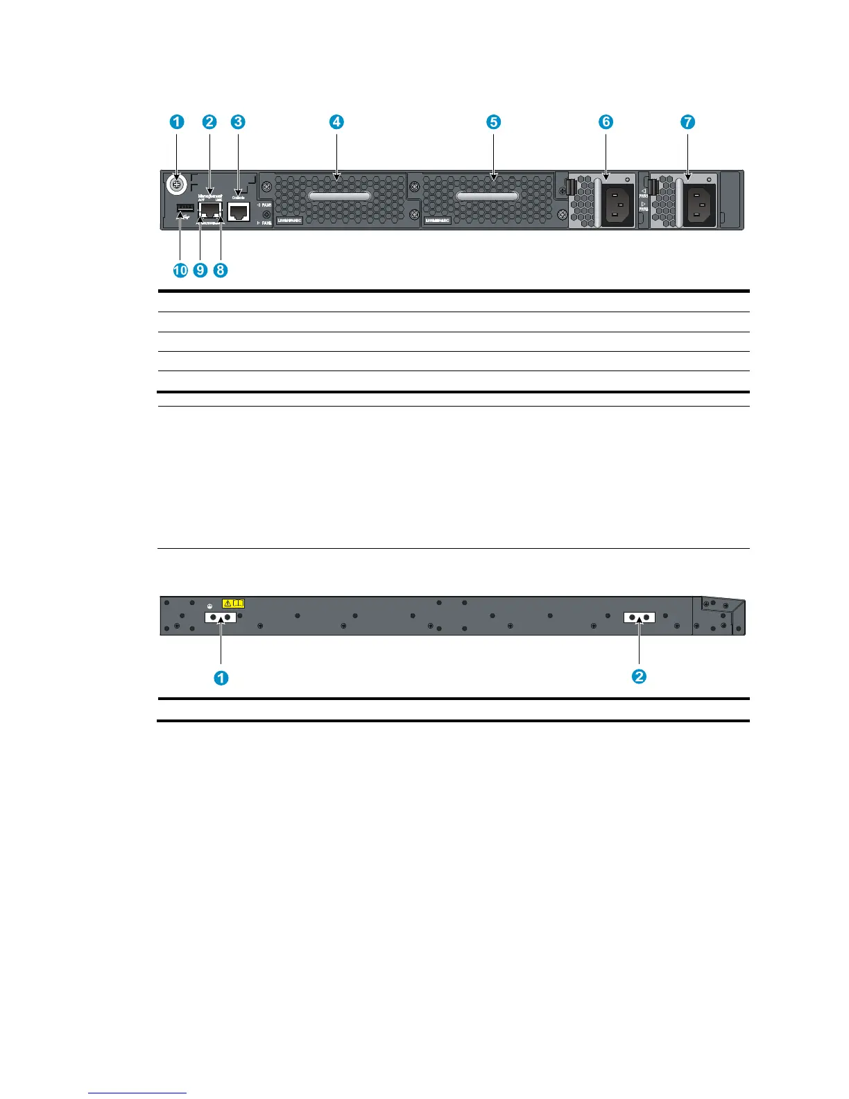
Figure 78 Rear panel
(1) Grounding screw (auxiliary grounding point 2) (2) Management Ethernet port
(3) Console port (4) Fan tray slot 1
NOTE:
• The 5800AF-48G switch comes with the power supply slots empty and the filler modules for the slots as
accessory. You can install one or two power supplies for the switch as needed. In this figure, two 650
AC power supplies are installed.
• The 5800AF-48G switch also comes with the fan tray slots empty. You must install two fan trays for the
5800AF-48G for adequate heat dissipation, and their models must be the same. In this figure, two
LSWM1FANSC fan trays are installed.
Figure 79 Left side panel
(1) Primary grounding point (2) Auxiliary grounding point 1