19
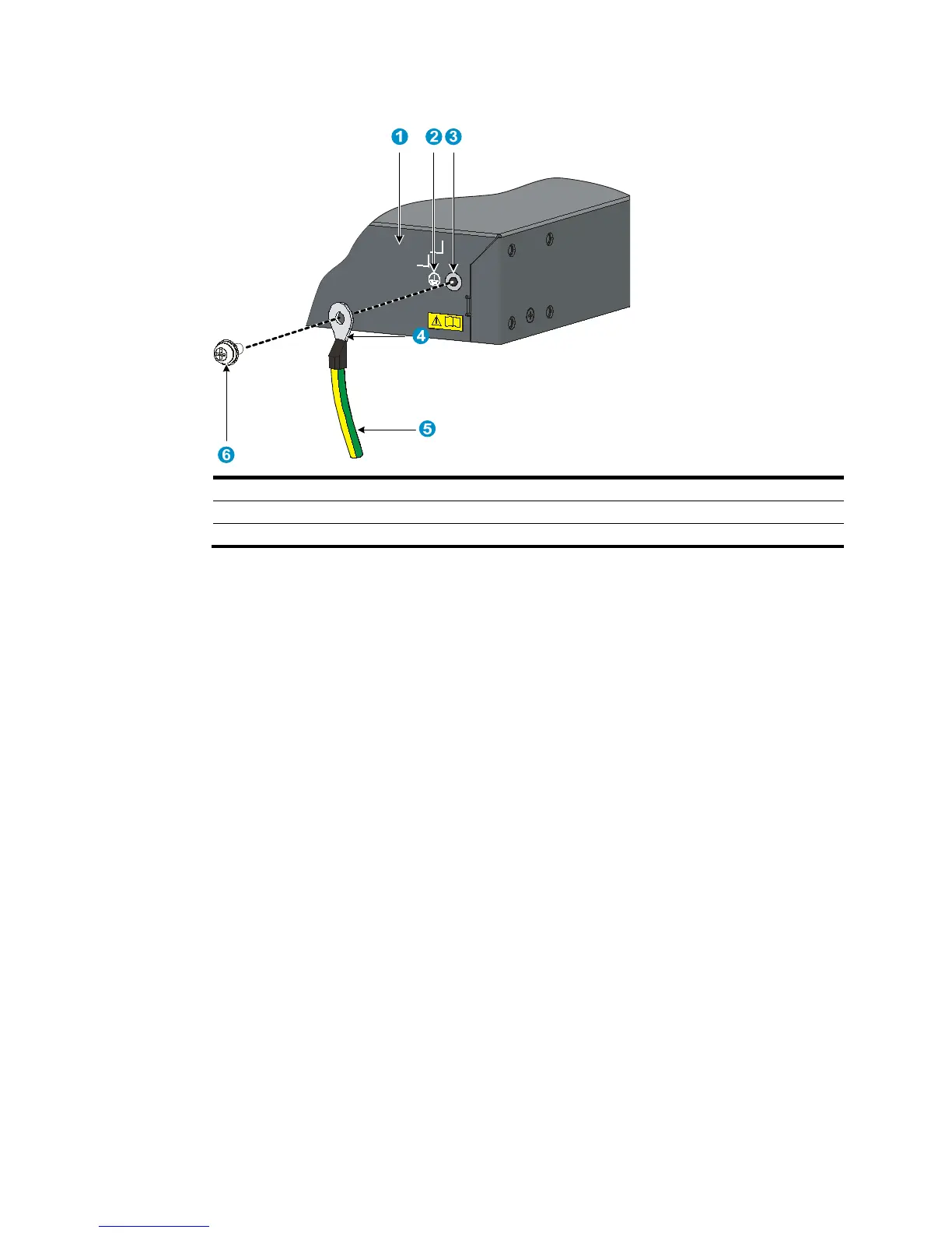
Figure 21 Connecting the grounding cable to the grounding hole of switch
(1) Chassis rear panel (2) Grounding sign
(3) Groundin
screw
4. Remove the hex nut of a grounding post on the grounding strip.
5. Cut the grounding cable as appropriate for connecting to the grounding strip.
6. Peel 5 mm (0.20 in) of insulation sheath by using a wire stripper, and insert the bare metal part
through the black insulation covering into the end of the ring terminal.
The switch comes with two ring terminals. Select the ring terminal appropriate to the size of the
grounding post.
7. Secure the metal part of the cable to the ring terminal with a crimper, cover the joint with the
insulation covering, and heat the insulation covering with a blow dryer to completely cover the
metal part.
8. Connect the ring terminal to the grounding post of the grounding strip, and fasten it with the
removed hex nut.