10
3. If the mounting brackets are in the rear mounting position, align the chassis rails with the screw
holes at the front of the side panels (see Figure 8). If th
e mounting brackets are in the front
mounting position, align the chassis rails with the screw holes at the rear of the side panels
(see Figure 9).
4. Use M4
screws (supplied with the switch) to fix the chassis rails to the chassis.
Connecting the grounding cable to the switch chassis
CAUTION:
The primary grounding point and auxiliary grounding point are located on the left side panel. If you
use either of the grounding points, you must connect the grounding cable to the grounding point before
you mount the switch in the rack.
To connect the grounding cable to a chassis grounding point:
1. Select a grounding point, for example, the primary grounding point.
2. Remove the grounding screws from the primary grounding point. (You can use the screws for
connecting to the primary grounding point or the auxiliary grounding point.)
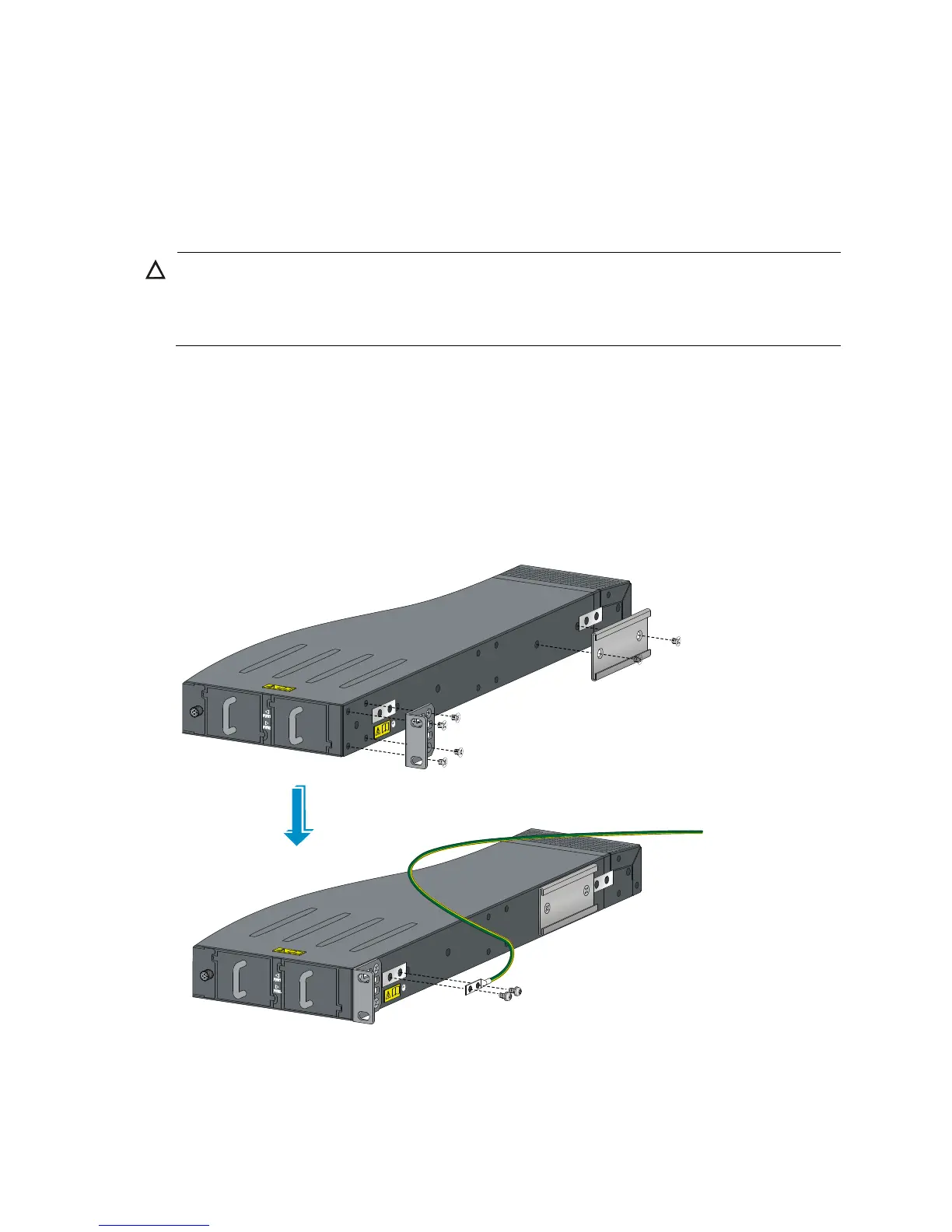
3. Align the two-hole grounding lug at one end of the cable with the grounding holes of the
grounding point, insert the grounding screws into the holes, and tighten the screws with a
screwdriver to fix the grounding lug to the chassis, as shown in Figure 8.
Figure 8 Attaching th
e rear mounting brackets, chassis rails, and the grounding cable to the chassis

 Loading...


