49
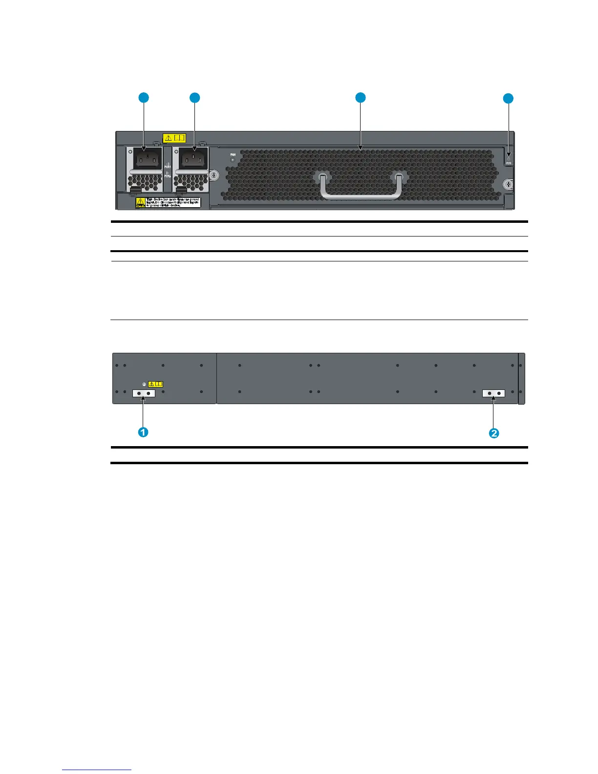
Figure 50 Rear panel
(1) Power supply slot 1 (PWR1) (2) Power supply slot 2 (PWR2)
(3) Fan tray slot (4) System status LED (SYS)
NOTE:
Each of the 96G model and 96G TAA model switches comes with the fan tray slot covered by a filler
panel and the power supply slots installed with filler modules. In this figure, two 650W AC power
supplies (JC680A) and one back-to-front airflow fan trays (JC695A) are installed.
Figure 51 Left side panel
(1) Primary
point
Cooling system
The cooling system of the switch comprises the air vents in the chassis, fan tray, and built-in fans of
power supplies. To guarantee the performance of this cooling system, consider the ventilation design
for the installation site when you choose a fan tray assembly and plan the installation site for the
switch.
Cooling system of the 48G model/48G TAA model
• When a back-to-front airflow fan tray (JC692A) is used, ambient air flows in through the air
vents in the fan tray panel and the power supply panels, circulates through the chassis and the
power supplies, and exhausts at the port side, as shown in Figure 52.
• W
hen a front-to-back airflow fan tray (JC693A) is used, ambient air flows in through the air
vents in the port-side panel and the power supply panels, circulates through the chassis and the
power supplies, and exhausts through the air vents in the fan tray panel, as shown in Figure 53.
1 2
3
4

 Loading...


