48
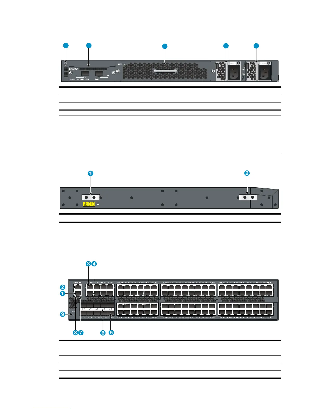
Figure 47 Rear panel
(1) System status LED (SYS) (2) Expansion interface card slot
(3) Fan tray slot (4) Power supply slot 1 (PWR1)
(5) Power supply slot 2 (PWR2)
NOTE:
Each of the 48G model and 48G TAA model switches comes with the expansion interface card slot and
the fan tray slot covered by filler panels and the power supply slots installed with filler modules. In this
figure, two 650W AC power supplies (JC680A), one back-to-front airflow fan tray (JC692A), and one
LSPM2SP2P (JD368B) expansion interface card are installed.
Figure 48 Left side panel
(1) Primary
Ethernet port (4) 10/100/1000Base-T -Ethernet port LED
(5) SFP+ port (6) SFP+ port LED
(7) LINK LED for the mana

 Loading...


