37
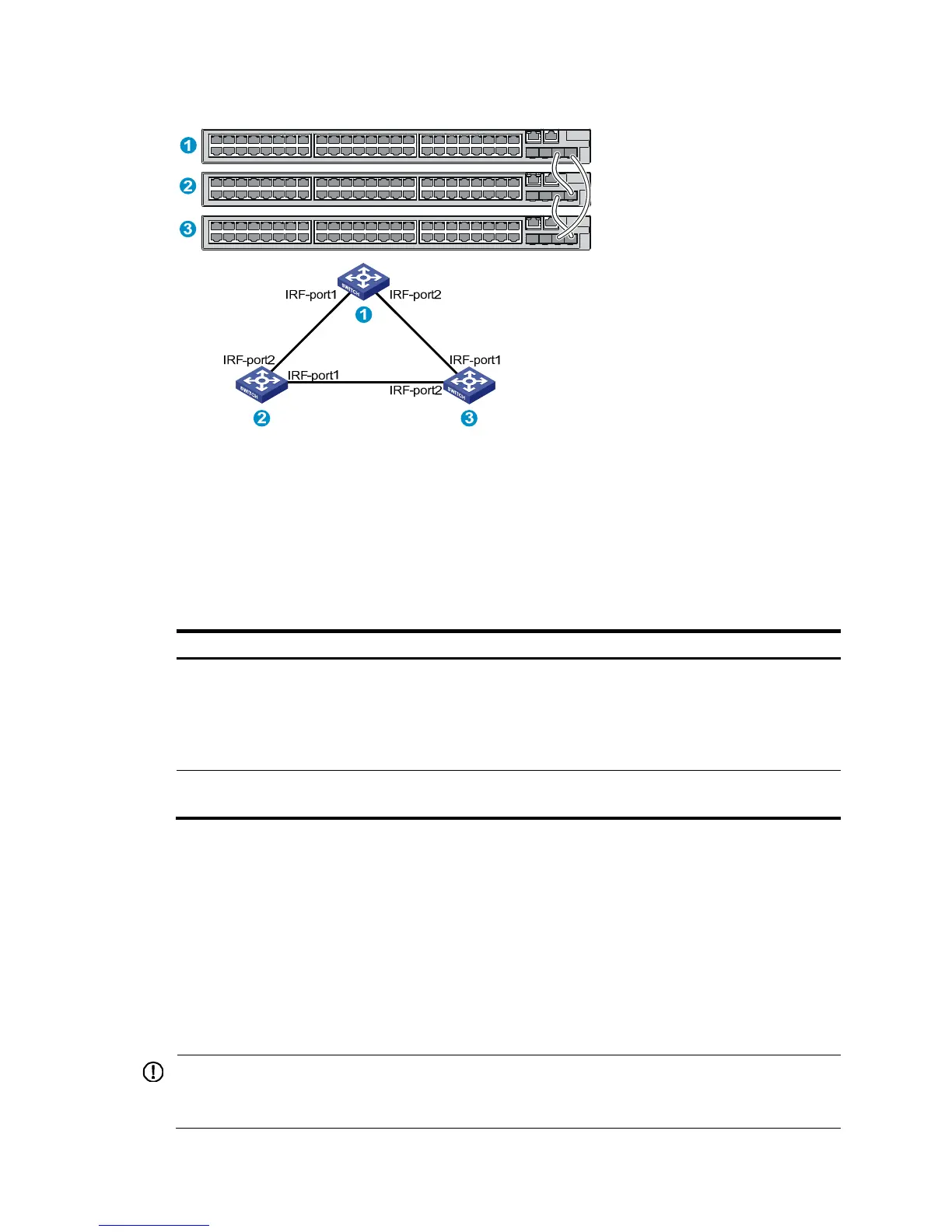
Figure 42 IRF fabric in ring topology
Identifying physical IRF ports on the member switches
Identify the physical IRF ports on the member switches according to your topology and connection
scheme.
Table 8 sho
ws the physical ports that can be used for IRF connection.
Table 8 Physical IRF port requirements
Switch chassis Candidate
orts
48G model/48G TAA
model
• 2 fixed SFP+ ports on the front panel
• 2 SFP+ ports on the 10 GE SFP+ expansion interface card at the rear
panel
NOTE:
You must purchase the expansion interface card separately.
96G model/96G TAA
model
10 fixed SFP+ ports on the front panel
Planning the cabling scheme
Use SFP+ cables or SFP+ transceiver modules and fibers to connect the IRF member switches. If the
IRF member switches are far away from one another, choose the SFP+ transceiver modules with
optical fibers. If the IRF member switches are all in one equipment room, choose SFP+ cables.
Table 21 and Table 22 list the SFP+ tr
ansceivers and SFP+ cables available for IRF connections.
The following subsections describe several HP recommended IRF connection schemes. All these
schemes use a ring topology.
IMPORTANT:
In these schemes, all physical IRF ports are located on the same side. If physical IRF ports are on
different sides, you must measure the distance between them to select an appropriate cable.

 Loading...


