11
Figure 9 Attaching the front mounting brackets and the chassis rails to the chassis
Installing the mounting brackets, chassis rails, and grounding
cable (for the 96G model/96G TAA model)
Each of the 96G model and 96G TAA model switches has one front mounting position near the
network ports and one rear mounting position near the power supplies. The switch also has one
primary grounding point with a grounding sign and one auxiliary grounding point. You use the
primary grounding point in most situations. If the primary grounding point fails or is not suitable for
the installation site, use the auxiliary grounding point.
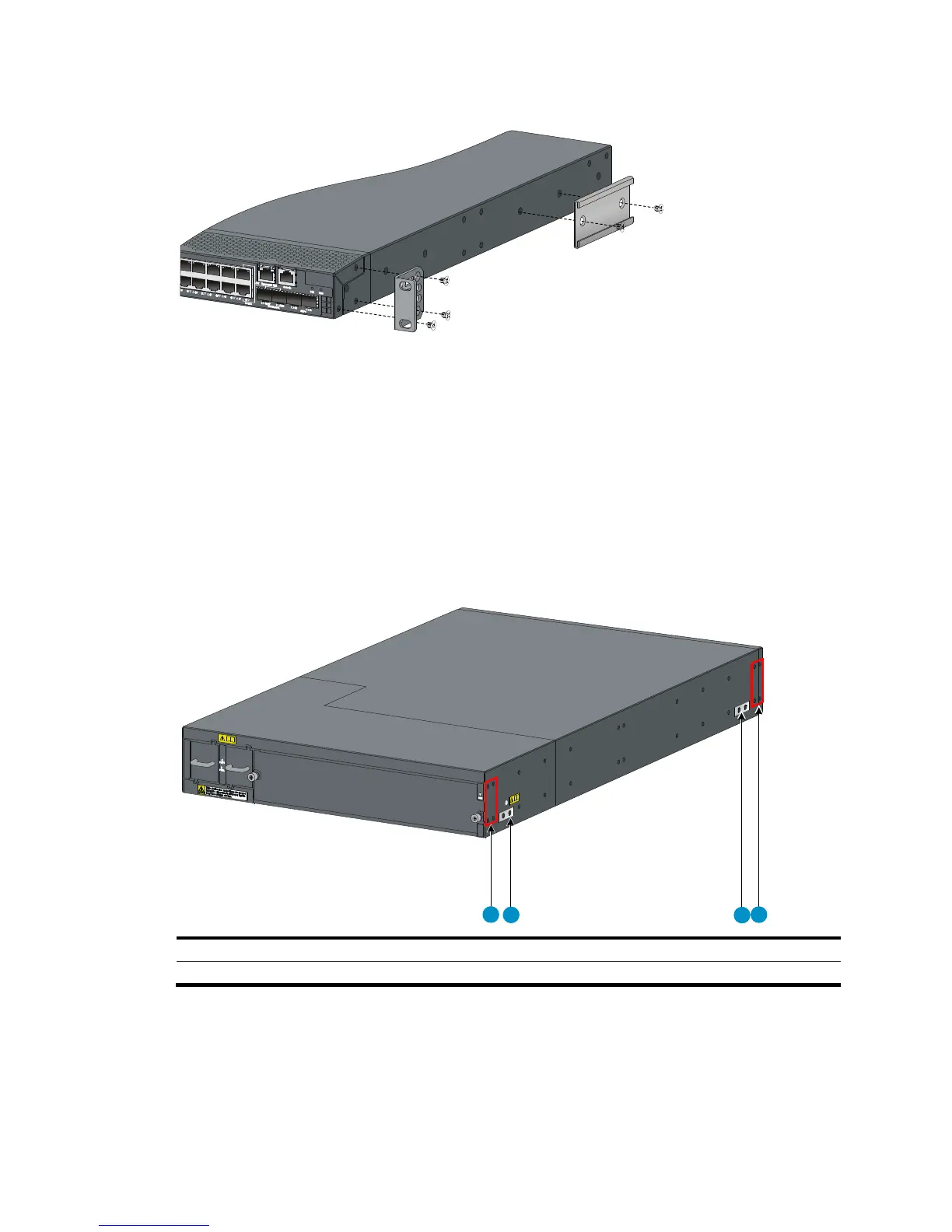
Figure 10 Identifying the mounting and grounding positions
(1) Rear mountin
point
(3) Auxiliary grounding point (4) Front mounting position
Attaching the mounting brackets and chassis rails to the switch chassis
Use the following procedure for both sides of the chassis.
To attach the mounting brackets and chassis rails to the switch chassis:
1. Align the mounting brackets with the screw holes in the rear mounting position (see Figure 11)
or front mo
unting position (see Figure 12).
1
2
4
3

 Loading...


