Connect network cables.
With the power still off (you’ll switch it on in the procedure “Plug in and
verify router hardware” on page 1-18), connect the network cables as de-
scribed in the documentation for the interface card(s). You should also
make sure that all network equipment and links are ready.
Caution Static discharge may damage equipment. Do not touch the router
connector pins or the cable connector pins.
Note For most interface cards (excluding, for example, the HP J2437A 4-Port
Token Ring Interface), if any port has no network attached, the port’s
Net Fail LED is lit after the router starts. To avoid unnecessary event log
messages, remember to disable that port when you configure the router.
For information on interpreting the Net Fail LED and other LED error
indications, refer to “Interpreting LED Error Patterns,” page 3-3.
To help keep the network cables orderly—and out of the way when inter-
face cards are being removed or installed—arrange the cables over the
bars at the right of the router.
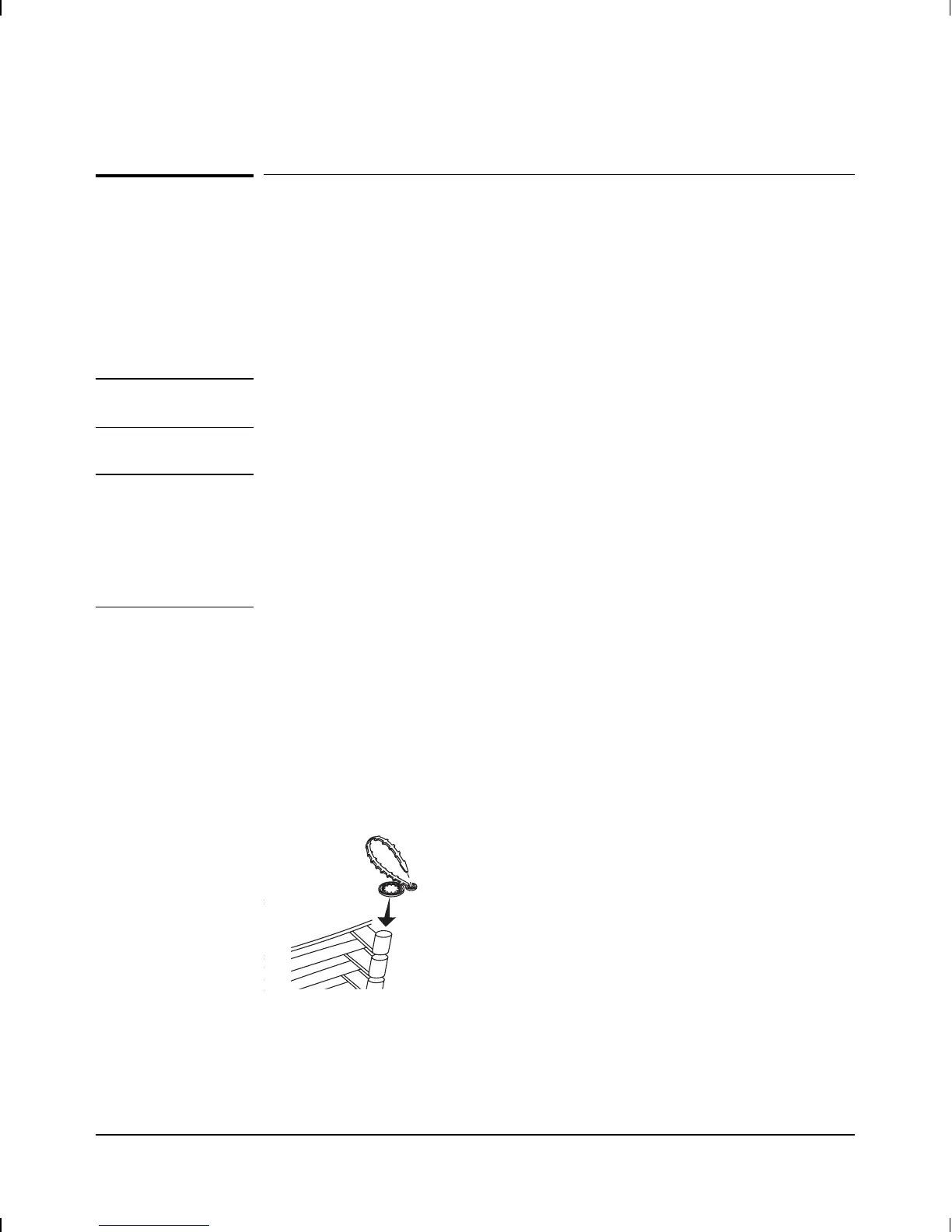
These cable-management bars have slots in them that you can use for
tie-wrapping the network cables. Included with each interface card is a
tie-wrap that you can use to wrap the cables and then attach the bundle
to the cable management bar, as shown in figure 1-10.
Figure 1-10. Cable-Management Bar and Tie-Wrap
Installation
Connect network cables.
1-15