11
8. One person lifts the chassis, supporting it with one hand underneath and the other hand holding
the front.
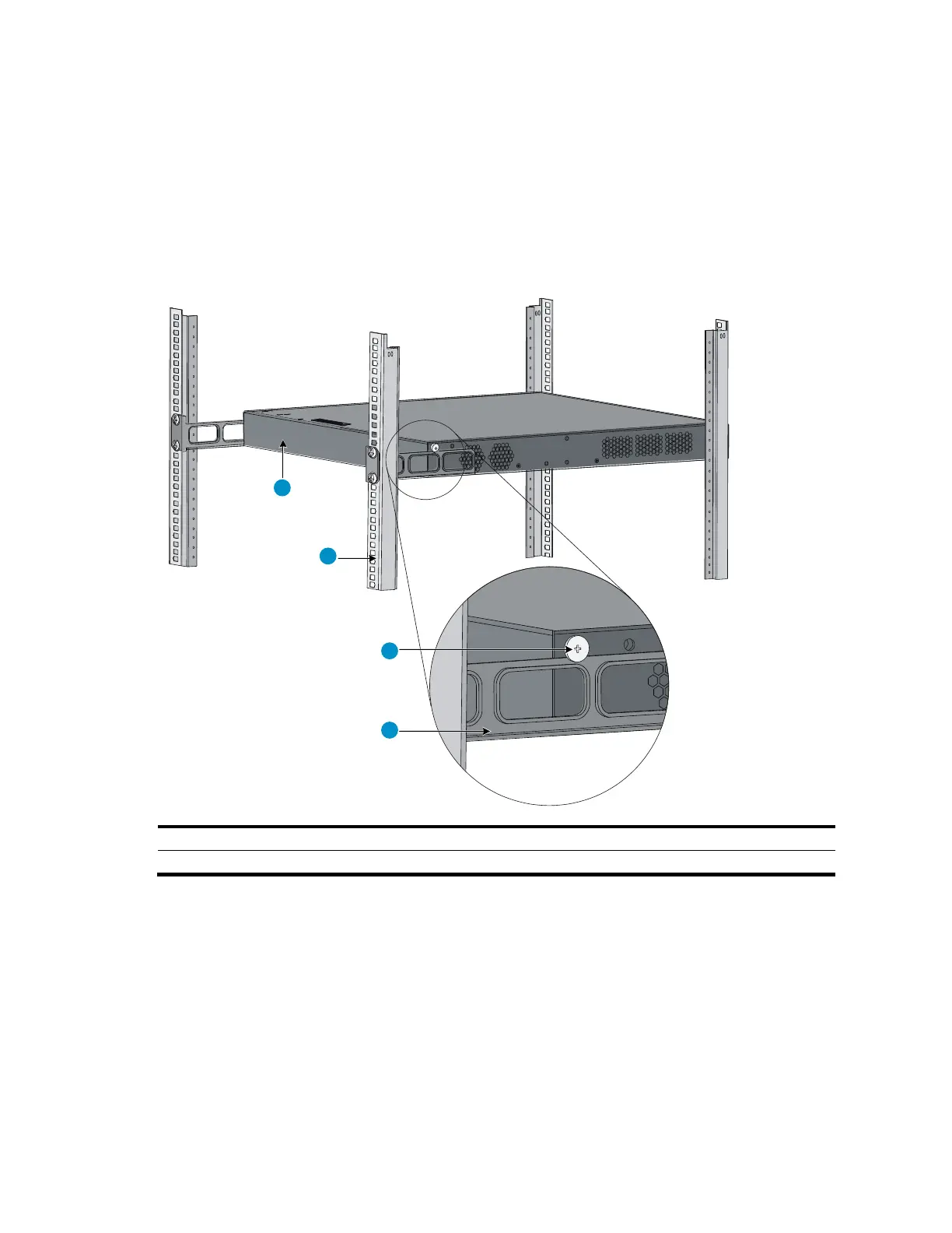
a. Gently push the chassis into the rack so that the load-bearing screws fit snugly over the upper
edges of the rear mounting brackets.
b. Verify that the load-bearing screws fit snugly over the upper edges of the rear mounting
brackets, as shown in Figure 8.
c. Continue to support the chassis until its front brackets are securely fastened to the rack.
Figure 8 Mount the switch in the rack
(2) Rear square-holed post
(4) Rear mounting bracket
9. The other person attaches the front brackets to the rack, as shown in Figure 9:
a. Align the oval holes in the front brackets with the mounting holes in the front rack posts.
b. Fasten the front mounting brackets to the front rack posts with user-supplied M6 screws.
10. Verify that front and rear mounting brackets have been installed correctly and switch is securely
mounted in the rack.

 Loading...


