Component identification 16
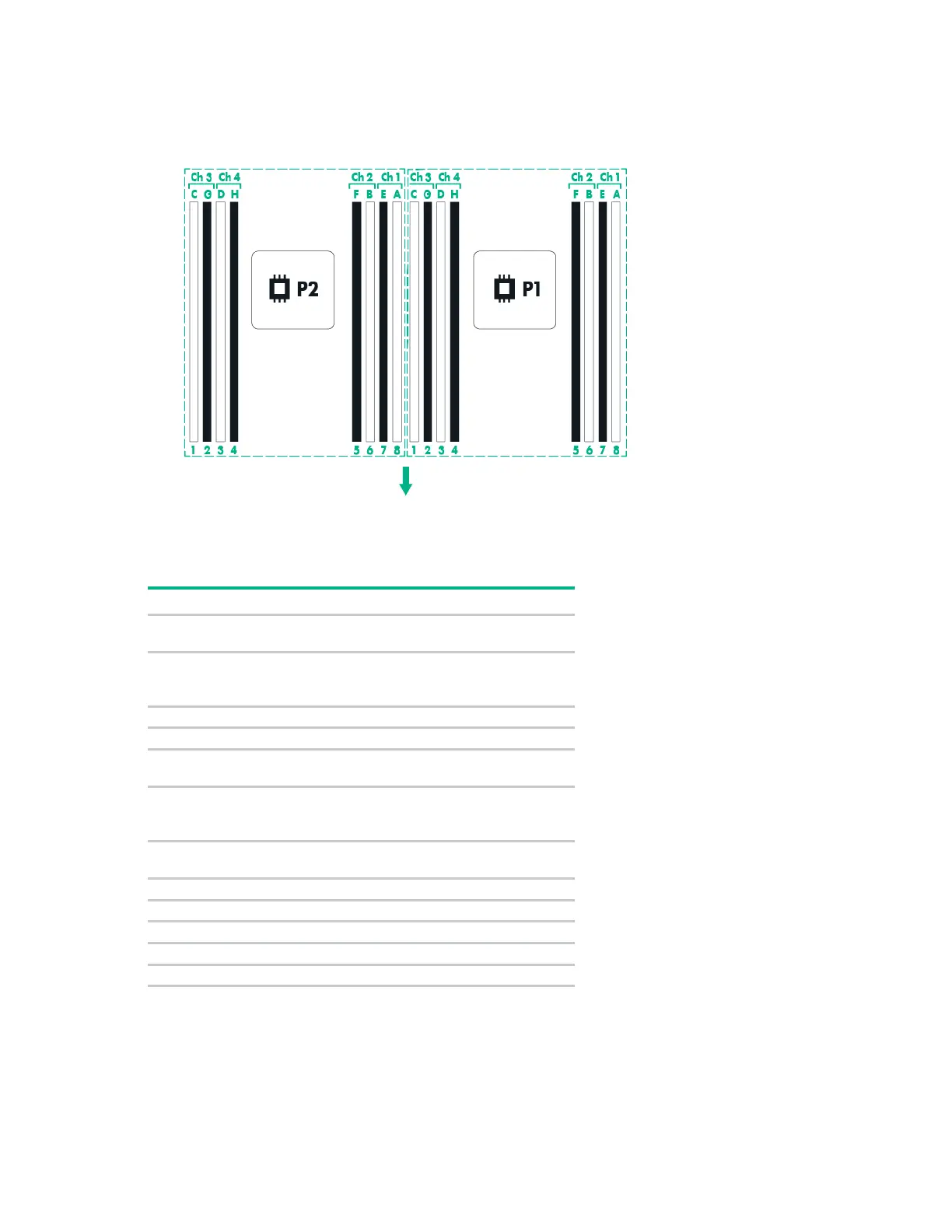
DIMM slot locations
DIMM slots are numbered sequentially (1 through 8) for each processor. The supported AMP modes use
the letter assignments for population guidelines.
The arrow points to the front of the server.
System maintenance switch
S1
Off = iLO 4 security is enabled.
On = iLO 4 security is disabled.
S2
Off = System configuration can be
changed.
On = System configuration is locked.
S5
Off = Power-on password is enabled.
On = Power-on password is disabled.
S6
On = ROM reads system
configuration as invalid.
S7
Off = Set default boot mode to UEFI.
On = Set default boot mode to legacy.
To access the redundant ROM, set S1, S5, and S6 to On.
When the system maintenance S6 switch is set to the On position, the system will erase all system
configuration settings from both CMOS and NVRAM on the next reboot.
 Loading...