Hardware options installation 49
d.
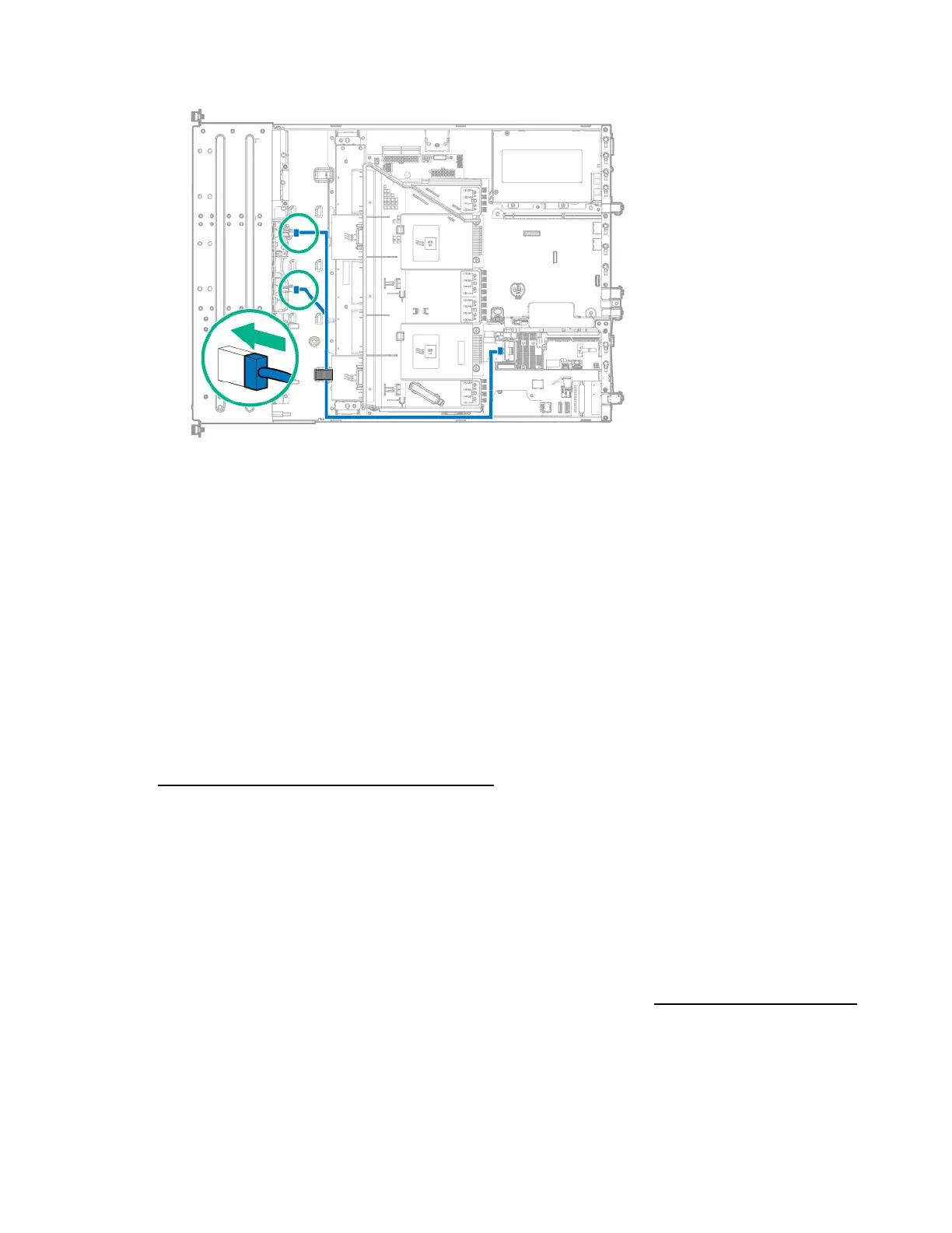
Secure the Mini-SAS Y-cable in the right front chassis cable clip.
12. Install the access panel (on page 25).
13. If removed, install the security bezel ("Security bezel option" on page 41).
14. Do one of the following:
o Slide the server into the rack.
o Install the server into the rack ("Installing the server into the rack" on page 35).
15. Power up the server (on page 20).
16. Install the drives ("Drive options" on page 41).
12-bay LFF hot-plug drive enablement option
This section provides instructions for installing the 4-bay LFF hot-plug drive cage backplane option, which
converts the 8-bay LFF hot-plug drive configuration to a 12-bay LFF hot-plug drive model. This hardware
option might require a power supply with a higher wattage rating. To accurately estimate the power
consumption of your server and select the appropriate power supply and other system components, see
the Hewlett Packard Enterprise Power Advisor website
(http://www.hpe.com/info/poweradvisor/online).
To maintain optimal thermal conditions when installing a P-series Smart Array Controller in a 12-bay LFF
drive configuration, Hewlett Packard Enterprise recommends the following guidelines:
• When installing only one controller board, install the board in slot 2 of either the 2-slot or the 3-slot
PCI riser cage assembly installed in the primary PCIe riser location ("PCI riser cage assembly
options" on page 88).
• When installing two controller boards, install the controller boards in slots 2 and 3 of the 3-slot PCI
riser cage assembly installed in the primary PCIe riser location ("PCI riser cage assembly options"
on page 88).
For more information about product features, specifications, options, configurations, and compatibility,
see the product QuickSpecs on the Hewlett Packard Enterprise website (http://www.hpe.com/info/qs).
To install the component:
1. Power down the server (on page 20).
2. Remove all power:
a. Disconnect each power cord from the power source.
 Loading...