Removal and replacement procedures 54
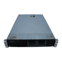
4. Apply all the grease to the top of the processor in the following pattern to ensure even distribution.
5. Install the heatsink ("Heatsink" on page 50).
6. Install the system board assembly (on page 31).
7. Install the chassis cover (on page 28).
8. Connect each power cord to the server.
9. Connect each power cord to the power source.
10. Press the Power On/Standby button.
The server exits standby mode and applies full power to the system. The system power LED changes
from amber to green.
System board
CAUTION: To avoid ESD damage, when removing electrostatic-sensitive components from the
failed system board, place the components on a static-dissipating work surface or inside separate
antistatic bags.
To remove the system board:
1. Power down the server (on page 24).
2. Disconnect the power cord from the AC source.
3. Disconnect the power cord from the server.
4. Remove the chassis cover (on page 27).
5. Remove the system board assembly.
WARNING: To reduce the risk of personal injury from hot surfaces, allow the heatsink to cool
before touching it.
CAUTION: Heatsink retaining screws should be tightened or loosened in diagonally opposite
pairs (in an "X" pattern). Do not overtighten the screws as this can damage the board, connectors,
or screws. Use the wrench supplied with the system to reduce the possibility of overtightening the
screws.
6. Remove the heatsink:
 Loading...