3. Remove the fan (see Fan on page 18).
4. Remove the heat sink (see Heat sink on page 19).
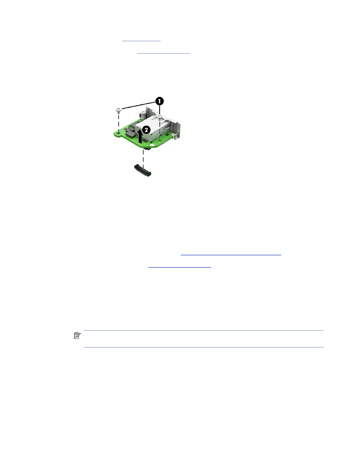
Remove flex I/O module:
■
Remove the two Phillips screws that secure the module to the inside back of the computer (1), and
then lift the module to disconnect it from the connector on the system board (2).
To install flex I/O module, reverse the removal procedure.
Riser assembly and expansion cards
To remove expansion cards and the riser assembly, use these procedures.
Before removing riser assembly, follow these steps:
1. Prepare the computer for disassembly (see Preparation for disassembly on page 17).
2. Remove the access panel (see Access panel on page 17).
Remove riser assembly:
1. To remove the riser assembly from the computer:
a. Loosen the Phillips screw (1).
b. Lift at the two locations marked in blue (2) to release the riser assembly from the computer.
The riser assembly is installed in the expansion card slot on the system board.
NOTE: If the riser assembly has a card with a cable that connects to the system board, be
sure not to prematurely pull the cable out of the system board connector.
Riser assembly and expansion cards
25
 Loading...