Table 5-7 Heat sink descriptions and part numbers (continued)
Description Spare part number
For use with system boards equipped with a graphics subsystem with discrete memory and an Intel
i-7 or Intel i-6 processor
N51005-001
For use with system boards equipped with a graphics subsystem with UMA memory N10925-001
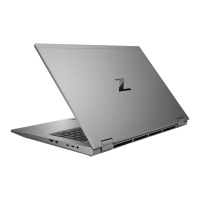
Before removing the heat sink, follow these steps:
1. Prepare the computer for disassembly (see Preparation for disassembly on page 40).
2. Remove the bottom cover (see Bottom cover on page 40).
3. Disconnect the battery cable from the system board (see Battery on page 46).
Remove the heat sink:
1. Release the tape (1) that secures the memory module shield to the heat sink.
2. In the order indicated on the heat sink, loosen the seven Phillips captive screws (2) that secure the
heat sink to the computer.
3. Remove the heat sink (3) from the computer.
4. Inspect the thermal material on the surfaces of the system board and the heat sink each time the
heat sink is removed. If the thermal pad is torn, missing part of the pad, or dirty, or if the thermal
paste is dirty, thoroughly clean the thermal material from the surfaces of the system board and the
heat sink. The following illustration shows the replacement thermal material locations.
Thermal paste is used on the system board processor (1) and on the heat sink area (2) that services
it. Thermal paste is also used on the VGA component (3) and on the heat sink area (4) that services
it.
Thermal pads are used on multiple system board components (5) and on the heat sink areas (6) that
service them.
50
Chapter 5 Removal and replacement procedures for authorized service provider parts
 Loading...