4. Remove the battery (see Battery on page 46).
5. Remove the fans (see Fans on page 49).
6. Remove the heat sink (see Heat sink on page 49).
7. Remove the system board (see System board on page 62).
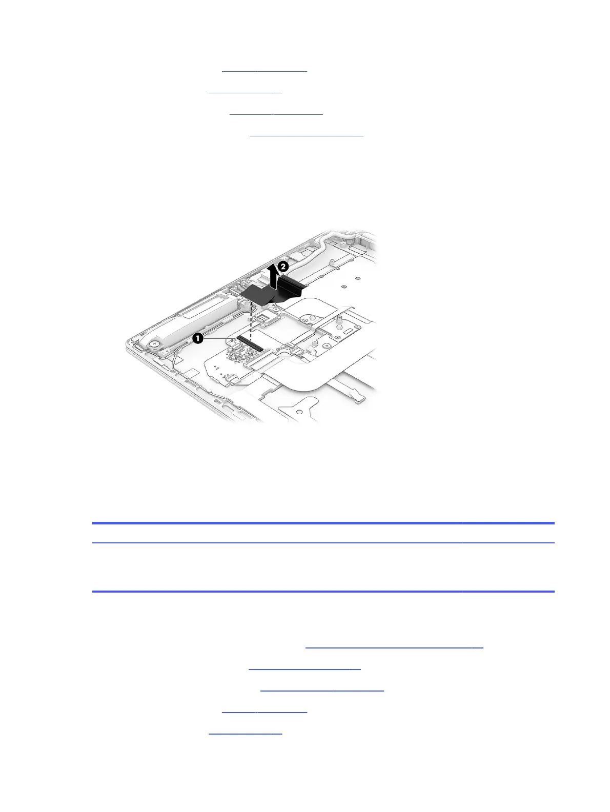
Remove the transfer board cable:
1. Release the ZIF connector (1) the transfer board cable is connected to, and then disconnect the
transfer board cable from the transfer board.
2. Remove the transfer board cable (2) from the computer.
To install the transfer board cable, reverse the removal procedure.
Transfer board
To remove the transfer board, use this procedure and illustration.
Table 5-11
Transfer board description and part number
Description Spare part number
Transfer board (includes double-sided adhesive)
NOTE: The transfer board spare part kit does not include the transfer board cable. The transfer
board cable is included in the Cable Kit, spare part number N08556-001.
N10919-001
Before removing the transfer board, follow these steps:
1. Prepare the computer for disassembly (see Preparation for disassembly on page 40).
2. Remove the bottom cover (see Bottom cover on page 40).
3. Remove the solid-state drive (see Solid-state drive on page 42).
4. Remove the battery (see Battery on page 46).
5. Remove the fans (see Fans on page 49).
70
Chapter 5 Removal and replacement procedures for authorized service provider parts
 Loading...