Introducing the switches | 24
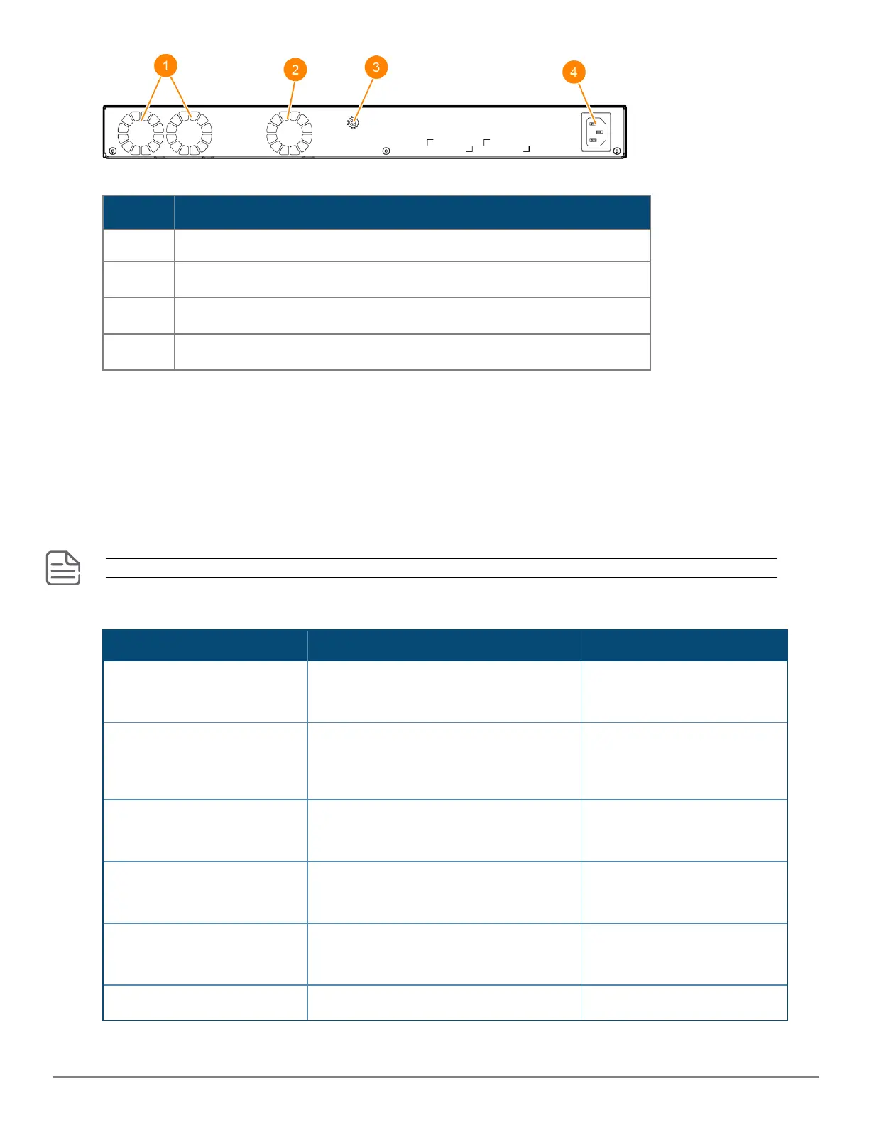
Label Description
1 System Fans
2 Integrated power supply fan
3 Ground lug
4 AC power inlet
Table 20: Back of the 6200F Switch: Label and Description
LEDs on the back of the switches
This section describes the LEDs on the back of the switch. When the back LED on the front of the unit is
blinking a fault, the user can look at the back of the switch to find the corresponding blinking LED for
the faulted fan or power supply. If a user installs a second power supply and did not turn on the power
(PSU module status = OFF), the back LED will blink orange.
Fan requirements
This section is only applicable to the 6200M switches. Switches in the 6200F family have internal, fixed fans.
Table 1: Fan requirements for 6200Mswitches
Switches Fan Tray 1 Fan Tray 2
HPEAruba Networking CX
6200M 36G 12SR5 Class6 PoE
4SFP+ switch (R8Q71A)
Required Optional
HPEAruba Networking CX
6200F 12G Class4 PoE
2G/2SFP+ 139W TAA switch
(R8V12A)
Required Optional
HPEAruba Networking CX
6200M 48G 4SFP+ switch
(R8Q69A)
Required Optional
HPE Aruba Networking CX
6200M 48G 4SFP+ TAA switch
(R8V10A)
Required Optional
HPEAruba Networking CX
6200M 24G 4SFP+ switch
(R8Q67A)
Required Optional
HPEAruba Networking CX Required Optional
 Loading...


